Operating Instructions Scanner IDM
Operation
Page 22 of 36
R. STAHL HMI Systems GmbH / OI_Scanner_IDM_en_V_01_00_04.docx / 29.01.2016
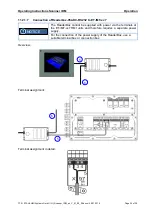
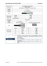
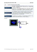
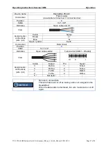
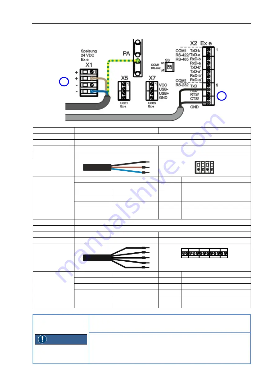
Terminal assignment in detail:
Device name
ReaderBox-054-DC-RS232
HMI ET-/MT-xx6
Connection
Power supply
Position
6
Cable
3 x 1 mm²
-
Definition
Open cable end X1
Terminal X1 (VDC)
View
Assignments /
connections
(wire / pin)
Cable
Signal
Pin
Signal
-
-
1
+24 VDC
Brown
+ VDC
2
+24 VDC
-
-
3
GND
Blue
GND
4
GND
Green / yellow
Earth
PA
PA connection
(Equipotential bonding)
Connection
Data circuit
Position
5
Cable
5 x 1 mm²
-
Definition
Open cable endX2
Terminal X2 (COM1 - RS-232)
View
13
9
1
Assignments /
connections
(wire / pin)
Cable
Signal
Pin
Signal
2 *
N.V. **
9
TxD
1
TxD
10
RxD
4 *
N.V. **
11
RTS/
5 *
N.V. **
12
CTS/
3
GND
13
GND
*
The wires of the X2 data circuit of the ReaderBox that are
marked with an asterisk are not needed and must be cut off at
the cable end.
N.V.
=
unused wire
**
This wire has been cut off ex-factory and is not assigned in the
ReaderBox !
When the data cable is shortened, this wire must also be cut off
again.
NOTICE
5
6
Summary of Contents for IDM160
Page 35: ......

