background image

english 

Operating Instructions 

 I.S. Relay Module Type 9172     

13


6  Marking and technical data 


Type designation 

CE marking 

ATEX marking explosion protection  

  and 

  Testing authority and certificate number 

IECEX marking explosion protection  

  Certificate number 

Ambient temperature range 

9172/**-11-00 

c

0158


e

 II 3 (1) G Ex nA nC [ia Ga] IIC T4 Gc 

e

 II (1) D [Ex ia Da] IIIC 

BVS 04 ATEX E 097 X  

Ex nA nC [ia Ga] IIC T4 Gc and [Ex ia Da] IIIC 

IECEx BVS 09.0002X  

-

20 °C … +70 °C 

(See chapter 8) 

Safety data 

9172/*0-11-00 

9172/*1-11-00 

9172/*2-11-00 

Coil circuit 
max. voltage / max. current, U

i / 

I

i


30 V / 150 mA 

30 V / 150 mA 

max. power, P

i


1,3 W 

1,3 W 

Contacts 
max. voltage / max. current, U

i / 

I

i


125 V AC / 4 A 
125 V DC / 0,25 

60 V DC / 0,3 A 
30 V DC / 4 A 

125 V AC / 4 A 
125 V DC / 0,25 

60 V DC / 0,3 A 
30 V DC / 4 A 

max. power, P

i


100 VA 

100 VA 

internal capacity, C

i

 / inductance, L

i


negligible 

negligible 

negligible 

Insulation voltage U

m


253 VAC  

253 VAC 

See EC-type examination certificate for further information and value combinations 

Technical data (extract from the data sheet) 
Coil circuit 


   Control voltage U

N


Ex i:  
12...30 V DC 

12...31,2 V DC 

Ex i:  
12...30 V DC 

   Current consumption at 12 V 

< 20 mA  

< 20 mA 

< 20 mA 

Contact circuit (changeover) 
   Maximum load DC  *) 


 Maximum load AC  *) 

     *) If installed in Zone 2 / Div. 2 max. 125 V AC/DC


220 V / 0,1 A 
125 V / 0,25 A 
60 V / 0,3 A 
 
250 V / 0,4 A / 100 VA 
125 V / 0,8 A / 100 VA 
30 V / 3,3 A / 100 VA 

Ex i: 
125 V / 0,25 A 
60 V / 0,3 A 
30 V / 4 A 
 
125 V / 4 A  

Ex i: 
125 V / 0,25 A 
60 V / 0,3 A 
30 V / 4 A 
 
125 V / 4 A  

Ambient conditions 


  Operating temperature 

-20...+70 °C 

  Storage temperature 

-40...+80 °C 

  Relative humidity (no condensation) 

< 95 % 

 
Additional technical data can be found in the current data sheet. (www.stahl.de) 


Please  consult  the  manufacturer  before  operating  under  conditions  which  deviate  from 
the standard operating conditions. 


Summary of Contents for ispac 9172

Page 1: ...Typ Type 9172 Ex i Relaismodul I S Relay Module Betriebsanleitung Operating Instructions...

Page 2: ...aratur und Instandhaltung 10 12 Zubeh r und Ersatzteile 10 Content 1 General information 11 1 1 Manufacturer 11 2 Symbols used 11 3 Safety instructions 11 4 Conformity to standards 12 5 Function 12 6...

Page 3: ...fasst Es erg nzt die entsprechenden Vorschriften zu deren Studium das verantwortliche Personal verpflichtet ist Bei Arbeiten in explosionsgef hrdeten Bereichen h ngt die Sicherheit von Personen und An...

Page 4: ...z aufheben Verwenden Sie das Ger t bestimmungsgem nur f r den zugelassenen Einsatzzweck siehe Funktion Warnung Durch fehlerhaften oder unzul ssigen Einsatz sowie das Nichtbeachten der Hinweise dieser...

Page 5: ...1 3 W Kontakte max Spannung max Strom Ui Ii 125 V AC 4 A 125 V DC 0 25 A 60 V DC 0 3 A 30 V DC 4 A 125 V AC 4 A 125 V DC 0 25 A 60 V DC 0 3 A 30 V DC 4 A max Leistung Pi 100 VA 100 VA innere Kapazit t...

Page 6: ...Ausgang Kanal 2 aktiviert 8 Anordnung und Montage 8 1 Ma zeichnung 8 2 Installation Die Ger te sind au erhalb explosionsgef hrdeter Bereiche zu installieren Die Ger te sind auch f r den Betrieb in ex...

Page 7: ...hl der pac Bus Elemente zusammenstecken pac Bus Elemente auf Hutschiene aufrasten Klemmenset am Anfang und am Ende einstecken pac Bus ist montiert 9 3 2 Montage Demontage auf Hutschiene Montage Beim A...

Page 8: ...eh uses muss dabei auf die Au enkante des pac Tr gers gesetzt werden Danach das Ger t einschwenken bis roter Rasthebel einrastet Der rote Rasthebel muss eingerastet sein Demontage Rasthebel 1 mit eine...

Page 9: ...9172 1 11 00 Typen 9172 2 11 00 9 2 Einstellungen Keine 1 6 5 2 10 11 Hazardous area 1 2 1 2 Sicherer Bereich Safe area 14 15 Ex Bereich 12 13 1 3 4 6 5 2 10 11 Hazardous area 1 2 1 2 Sicherer Bereich...

Page 10: ...uns durchf hren zu lassen In Ausnahmef llen kann die Reparatur auch durch eine andere zugelassene Stelle erfolgen Die Ger te sind wartungsfrei F hren die beschriebenen Vorgehensweisen nicht zum gew ns...

Page 11: ...en installing and operating the device the following are to be observed The national installation and assembly regulations e g EN 60079 14 apply For SIL applications please observe the FMEDA report SI...

Page 12: ...e or non compliance with these instructions the intended protection can be impaired the warranty provision is invalidate on our part in these cases o No changes to the devices or components impairing...

Page 13: ...VA 100 VA internal capacity Ci inductance Li negligible negligible negligible Insulation voltage Um 253 VAC 253 VAC See EC type examination certificate for further information and value combinations T...

Page 14: ...ated 17 LED OUT2 amber Output channel 1 activated 8 Arrangement and fitting 8 1 Dimensions 8 2 Installation The device may be installed in Zone 2 Zone 22 or outside of the hazardous area In the case o...

Page 15: ...f pac Bus elements Snap the pac Bus segment on the DIN rail Assemble the terminal set at the beginning and the end of the pac Bus segment 9 3 2 Mounting Dismounting on DIN rail with or without pac Bus...

Page 16: ...d locking handle is locked Please check that the locking handle is locked Dismounting Put the screw driver into the red locking handle 1 and move the screw driver into the described direction Device w...

Page 17: ...Types 9172 1 11 00 Types 9172 2 11 00 9 2 Settings None 1 6 5 2 10 11 Hazardous area 1 2 1 2 Sicherer Bereich Safe area 14 15 Ex Bereich 12 13 1 3 4 6 5 2 10 11 Hazardous area 1 2 1 2 Sicherer Bereich...

Page 18: ...eptional cases repair may be performed by approved third parties The devices are maintenance free If the procedure described above does not obtain the desired result please contact your local R STAHL...

Page 19: ...19 EG Konformit tserkl rung EC Declaration of Conformity...

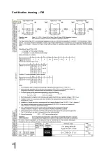
Page 20: ...20 Certification drawing FM...

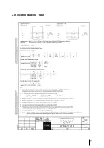
Page 21: ...21 Certification drawing CSA...

Page 22: ......

Page 23: ......

Page 24: ...R STAHL Schaltger te GmbH Am Bahnhof 30 74638 Waldenburg W rtt Germany www stahl de ID Nr 160372 9172601310 S BA 9172 004 de en 03 2013...

Reviews: