background image

DE
DE
DE
DE
DE
DE
DE
DE
DE
DE
DE
DE
DE
DE
DE
DE
DE
DE
DE
DE
DE
DE
DE
DE
DE

Betriebsanleitung

Additional languages www.r-stahl.com  

DE

Erdungsüberwachungsgerät

Reihe 8146/5075,  
Reihe 8150/5-V75

Summary of Contents for Series 8146/5075

Page 1: ...DE DE DE DE DE DE DE DE DE DE DE DE DE DE DE DE DE DE DE DE DE DE DE DE DE Betriebsanleitung Additional languages www r stahl com DE Erdungsüberwachungsgerät Reihe 8146 5075 Reihe 8150 5 V75 ...

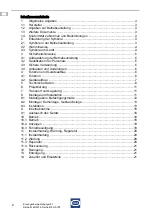
Page 2: ...ebsanleitung 5 3 2 Qualifikation des Personals 5 3 3 Sichere Verwendung 5 3 4 Umbauten und Änderungen 6 4 Funktion und Geräteaufbau 6 4 1 Funktion 6 4 2 Geräteaufbau 7 5 Technische Daten 8 6 Projektierung 11 7 Transport und Lagerung 11 8 Montage und Installation 11 8 1 Maßangaben Befestigungsmaße 12 8 2 Montage Demontage Gebrauchslage 13 8 3 Installation 13 9 Inbetriebnahme 18 9 1 Austausch des Ge...

Page 3: ...anleitung ist die englische Ausgabe Diese ist rechtsverbindlich in allen juristischen Angelegenheiten 1 3 Weitere Dokumente Datenblatt FMEDA Report SIL Dokumente in weiteren Sprachen siehe www r stahl com 1 4 Konformität zu Normen und Bestimmungen Zertifikate und EU Konformitätserklärung siehe www r stahl com Das Gerät verfügt über eine IECEx Zulassung Zertifikat siehe IECEx Homepage http iecex ie...

Page 4: ...ung führt zu schweren oder tödlichen Verletzungen bei Personen WARNUNG Gefahren für Personen Nichtbeachtung der Anweisung kann zu schweren oder tödlichen Verletzungen bei Personen führen VORSICHT Gefahren für Personen Nichtbeachtung der Anweisung kann zu leichten Verletzungen bei Personen führen HINWEIS Vermeidung von Sachschaden Nichtbeachtung der Anweisung kann zu einem Sachschaden am Gerät und ...

Page 5: ... elektrischer Anlagen IEC EN 60079 19 Gerätereparatur Überholung und Regenerierung 3 3 Sichere Verwendung Vor der Montage Sicherheitshinweise in dieser Betriebsanleitung lesen und beachten Sicherstellen dass der Inhalt dieser Betriebsanleitung vom zuständigen Personal voll verstanden wurde Gerät nur bestimmungsgemäß und nur für den zugelassenen Einsatzzweck verwenden Bei Betriebsbedingungen die du...

Page 6: ...ennbaren Flüssigkeiten und staubförmigen Produkten Das Gerät darf in den Zonen 1 2 21 22 sowie außerhalb explosionsgefährdeter Bereiche eingesetzt werden Arbeitsweise Die während der Be und Entladung entstehende elektrostatische Aufladung wird abgeleitet und der Stromkreis während des gesamten Vorgangs überwacht Die Überwachung basiert auf der Auswertung des Übergangswiderstandes vom Erdungsüberwa...

Page 7: ...kontaktes 3 Klimastutzen M25 M20 Klimastutzen zur Belüftung und zum Druckausgleich von Ex e Gehäusen 4 Kabelverschraubung M20 Blau Anschlussverbindung zwischen der blauen Klemme Pin 11 und der PA Schiene der Verladeplattform 5 Kabelverschraubung M20 Anschlussverbindung zwischen der PA Schiene der Verladeplattform und der PA Klemme des Erdungsgerätes 6 Kabelverschraubung M20 Anschluss der Erdungsza...

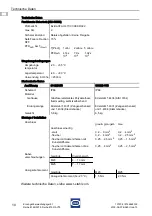
Page 8: ...II 2 1 G Ex db e ia Ga IIC T4 Gb E II 2 1 G Ex db eb ia Ga IIC T4 Gb E II 2 1 D Ex ia Da tb IIIC T80 C Db E II 2 1 D Ex ia Ga tb IIIC T80 C Db Bescheinigungen und Zertifikate Bescheinigungen IECEx ATEX Brasilien INMETRO Kasachstan TR Russland TR Weißrussland TR Schiffszertifikate DNV GL Weitere Parameter Installation in Zone 1 2 21 22 Technische Daten Elektrische Daten Stromversorgung Nennspannung...

Page 9: ...IIB 26 mF Max anschließbare Induktivität Lo IIC 350 mH IIB 1000 mH Innere Kapazität Ci 2 42 nF Innere Induktivität Li vernachlässigbar Sicherheits technische Maximalspannung 253 V Technische Daten Funktionsweise Zustand der Erdung Reaktion des Erdungs überwachungsgerätes 10938E00 Zange ist nicht angeschlossen Gerät im Ruhezustand Erdung fehlerhaft roter Leucht melder EIN grüner Leucht melder AUS S...

Page 10: ... Schutzart IP66 IP66 Material Gehäuse Glasfaserverstärktes Polyesterharz flammwidrig selbstverlöschend Edelstahl 1 4404 AISI 316L Erdungszange Edelstahl 1 4301 Zangenschenkel und 1 4034 Klemmbacke Edelstahl 1 4301 Zangenschenkel und 1 4034 Klemmbacke Gewicht 5 8 kg 6 5 kg Montage Installation Anschluss Kabel verschraubungen Anzugsdrehmoment Technische Daten T Proof 1 Jahr 2 Jahre 5 Jahre PFDAVG 4 ...

Page 11: ...ohe Umgebungstemperatur Nichtbeachten kann zu Sachschäden führen Schaltschrank so aufbauen und einrichten dass er immer innerhalb des zulässigen Temperaturbereichs betrieben wird GEFAHR Explosionsgefahr durch falsche Installation des Geräts Nichtbeachten führt zu schweren oder tödlichen Verletzungen Installation strikt nach Anleitung und unter Berücksichtigung der nationalen Sicherheits und Unfall...

Page 12: ...E DE DE DE DE DE DE DE DE DE DE DE DE DE DE DE DE DE DE Erdungsüberwachungsgerät Reihe 8146 5075 Reihe 8150 5 V75 8 1 Maßangaben Befestigungsmaße Maßzeichnungen alle Maße in mm Zoll Änderungen vorbehalten 08029E00 14867E00 Erdungsüberwachungsgerät 8146 5075 Erdungsüberwachungsgerät 8150 5 V75 ...

Page 13: ...onsgeschütztes elektrisches Betriebsmittel mit Schutzdach oder wand ausrüsten 8 2 1 Gebrauchslage 8 3 Installation 17202E00 17203E00 Gehäuse 8146 Gehäuse 8150 Das Erdungsüberwachungsgerät vertikal montieren Gehäuse mit 4 Schrauben befestigen siehe Befestigungsmaße Schrauben anziehen Bei Betrieb unter erschwerten Bedingungen wie insbesondere auf Schiffen sind zusätzliche Maßnahmen zur korrekten Ins...

Page 14: ...erwachungsgerät eine Zange mit normalen Kabel Spiralkabel oder einer Aufrollautomatik anschließen GEFAHR Explosionsgefahr durch falsche Auslegung der Kriech und Luftstrecken Nichtbeachten führt zu schweren oder tödlichen Verletzungen Erforderliche Kriech und Luftstrecken einhalten IEC EN 60079 7 beachten GEFAHR Explosionsgefahr durch zu hohe Spannung Nichtbeachten führt zu schweren oder tödlichen ...

Page 15: ... DE Erdungsüberwachungsgerät Reihe 8146 5075 Reihe 8150 5 V75 8 3 2 Prinzipschaltbild 18437E00 19411E00 Anschlussquerschnitte für anzuschließende Verdrahtung siehe Datenblatt Legende 1 Erdungsüberwachungsgerät 2 Stromversorgung 3 Potenzialfreier Hilfskontakt 4 PA Schiene der Verladeplattform 5 Erdungszange oder Aufrollautomatik Ex i Stromkreis ...

Page 16: ...sgerät und Verladeplattform sicherstellen Angaben im Kapitel Technische Daten beachten HINWEIS Anschluss der Erdungszange an das Erdungsüberwachungsgerät Ex i Stromkreis Nichtbeachten kann Sachschäden verursachen Adern braun und grün gelb werden in dem Anschlusskabel bzw in der Aufrollautomatik zusammengeführt und an der PA Klemme angeschlossen Ader blau wird an der Klemme 10 angeschlossen Widerst...

Page 17: ...ng auf ein annehmbares Maß verringert wird Widerstandswert kontrollieren Dauerhafte Flexibilität und ausreichend mechanische Festigkeit der Leiter und Verbindungen sicherstellen IEC Normen oder nationale sonstige Normen einhalten Zeitweilige Potentialausgleichsverbindungen umfassen Erdungsanschlüsse die an beweglichen Einheiten wie Trommeln Fahrzeugen und tragbaren Betriebsmitteln für die Kontroll...

Page 18: ...s 10 Betrieb 10 1 Betrieb Während des Betriebs leuchtet der grüne Leuchtmelder Er zeigt an dass die Erdungszange angeschlossen und die Erdung aktiv ist Somit ist eine sichere und korrekte elektrostatische Erdung während der Be und Entladung von brennbaren Flüssigkeiten und staubförmigen Produkten gewährleistet Zange von dem Aufhängungspunkt an der rechten Gehäuseseite abnehmen Zange an das zu erde...

Page 19: ...Ausgangsbeschaltung Bei Tankcontainern auf Gummipuffer achten die den Tank vom Gestell isolieren könnten Die Verbindung führt zu jedem metallischen Objekt führt zur Signalisierung einer ausreichenden Erdung Die Zange deshalb nur an das zu erdende Objekt oder den isolierten Aufhängepunkt am Gehäuse anklemmen Farbe Leuchtmelder leuchtet Leuchtmelder erloschen grün Gerät wird mit Hilfsenergie versorg...

Page 20: ... der untergeklemmten Leitungen Rissbildung und andere sichtbare Schäden am Gerätegehäuse und oder Schutzgehäuse Einhaltung der zulässigen Temperaturen gemäß IEC EN 60079 fester Sitz der Mutter 11 2 Wartung Mindestens 1 mal jährlich folgende Punkte überprüfen Zustands des Gehäuses und Leitungseinführungen Qualität aller Kontaktverbindungen Staub und Schmutz auf den Oberflächen des Gehäuses entferne...

Page 21: ...nen RMA Schein Gerät zusammen mit dem RMA Schein in der Verpackung an die R STAHL Schaltgeräte GmbH senden Adresse siehe Abschnitt 1 1 12 Reinigung Gerät nur mit einem Tuch Besen Staubsauger o ä reinigen Bei feuchter Reinigung Wasser oder milde nicht scheuernde nicht kratzende Reinigungsmittel verwenden Keine aggressiven Reinigungsmittel oder Lösungsmittel verwenden 13 Entsorgung Nationale und lok...

Page 22: ......

Page 23: ...EN EN EN EN EN EN EN EN EN EN EN EN EN EN EN EN EN EN EN EN EN EN EN EN EN Operating instructions Additional languages www r stahl com EN Grounding monitoring device Series 8146 5075 Series 8150 5 V75 ...

Page 24: ...nstructions Storage 5 3 2 Personnel Qualification 5 3 3 Safe Use 5 3 4 Modifications and Alterations 6 4 Function and Device Design 6 4 1 Function 6 4 2 Device Design 7 5 Technical Data 8 6 Engineering 11 7 Transport and Storage 11 8 Mounting and Installation 11 8 1 Dimensions Fastening Dimensions 12 8 2 Mounting Dismounting Operating position 13 8 3 Installation 13 9 Commissioning 18 9 1 Replacem...

Page 25: ...3 The original instructions are the English edition They are legally binding in all legal affairs 1 3 Further Documents Data sheet FMEDA Report SIL For documents in additional languages see www r stahl com 1 4 Conformity with Standards and Regulations See certificates and EC Declaration of Conformity www r stahl com The device has IECEx approval For certificate please refer to the IECEx homepage h...

Page 26: ...mpliance with the instruction results in severe or fatal injuries to persons WARNING Danger to persons Non compliance with the instruction can result in severe or fatal injuries to persons CAUTION Danger to persons Non compliance with the instruction can result in light injuries to persons NOTICE Avoiding material damage Non compliance with the instruction can result in material damage to the devi...

Page 27: ...ce of electrical installations IEC EN 60079 19 Equipment repair overhaul and reclamation 3 3 Safe Use Before mounting Read and observe the safety notes in these operating instructions Ensure that the contents of these operating instructions are fully understood by the personnel in charge Use the device in accordance with its intended and approved purpose only Always consult with R STAHL Schaltgerä...

Page 28: ...oading of combustible liquids and powdery products The device may be installed in Zones 1 2 21 22 and outside of hazardous areas Mode of operation The electrostatic charges generated during loading and unloading are eliminated and the circuit is monitored during the entire process Monitoring is based on the evaluation of the transition resistance from the grounding monitoring device to the object ...

Page 29: ...ather M25 M20 Breather used for ventilation and pressure equalization of Ex e enclosures 4 Cable gland M20 blue Connection between the blue terminal pin 11 and the equipotential bonding rail of the loading platform 5 Cable gland M20 Connection between the equipotential bonding rail of the loading platform and the equipotential bonding terminal of the grounding device 6 Cable gland M20 Connection o...

Page 30: ...1 G Ex db e ia Ga IIC T4 Gb E II 2 1 G Ex db eb ia Ga IIC T4 Gb E II 2 1 D Ex ia Da tb IIIC T80 C Db E II 2 1 D Ex ia Ga tb IIIC T80 C Db Certifications and certificates Certificates IECEx ATEX Brazil INMETRO Kazakhstan TR Russia TR Belarus TR Ship approval DNV GL Further parameters Installation in Zones 1 2 21 22 Technical Data Electrical data Power supply Rated voltage 110 to 230 V AC Nominal vo...

Page 31: ...IIC 3 6 mF IIB 26 mF Max connectable inductance Lo IIC 350 mH IIB 1000 mH Internal capacitance Ci 2 42 nF Internal inductance Li negligible Safety related maximum voltage 253 V Technical Data Operating mode State of grounding Reaction of the grounding monitoring device 10938E00 Clamp is not connected device not in use Grounding incorrect red indicator lamp ON green indicator lamp OFF Switching con...

Page 32: ...rial Enclosure Glass fibre reinforced polyester resin flame resistant Stainless steel 1 4404 AISI 316L Grounding clamp Stainless steel 1 4301 tong limbs and 1 4034 clamping jaw Stainless steel 1 4301 tong limbs and 1 4034 clamping jaw Weight 5 8 kg 6 5 kg Mounting Installation Connection Cable glands Tightening torque Technical Data T Proof 1 year 2 years 5 years PFDAVG 4 14 x 10 4 7 9 x 10 4 1 92...

Page 33: ...re of the devices installed in the cabinet Non compliance can result in material damage Install and adjust the cabinet in such a way that it is always operated within the permissible temperature range DANGER Explosion hazard due to incorrect installation of the device Non compliance results in severe or fatal injuries Carry out installation strictly according to the instructions and national safet...

Page 34: ...EN EN EN EN EN EN EN EN EN EN EN EN EN EN Grounding monitoring device Series 8146 5075 Series 8150 5 V75 8 1 Dimensions Fastening Dimensions Dimensional Drawings All Dimensions in mm inches Subject to Alterations 08029E00 14867E00 Grounding monitoring device 8146 5075 Grounding monitoring device 8150 5 V75 ...

Page 35: ...ure and explosion protected electrical equipment are used outdoors 8 2 1 Operating Position 8 3 Installation 17202E00 17203E00 Enclosure 8146 Enclosure 8150 Mount the grounding monitoring device vertically Fasten the enclosure using 4 screws see fastening dimensions Tighten the screws Operation under difficult conditions such as in particular on ships requires additional measures to be taken for c...

Page 36: ...p with normal cable spiral cable or an automatic winder to the grounding monitoring device DANGER Explosion hazard due to incorrect dimensioning of creepage distances and clearances Non compliance results in severe or fatal injuries Adhere to the required creepage distances and clearances Observe IEC EN 60079 7 DANGER Explosion hazard caused by voltage that is too high Non compliance results in se...

Page 37: ...eries 8146 5075 Series 8150 5 V75 8 3 2 Schematic Diagram 18437E00 19411E00 For information on the connection cross sections of the wiring to be connected refer to the data sheet Legend 1 grounding monitoring device 2 power supply 3 potential free auxiliary contact 4 equipotential bonding rail of the loading platform 5 grounding clamp or automatic winder Ex i electric circuit ...

Page 38: ...nd the loading platform Please observe the information provided in the Technical Data chapter NOTICE Connecting the grounding clamp to the grounding monitoring device Ex i electric circuit Non compliance can result in material damage Brown and green yellow wires are merged in the connection cable or the automatic winder and then connected to the equipotential bonding terminal The blue wire is conn...

Page 39: ...ed procedure which reduces the risk of sparking to an acceptable level Check resistance value Ensure that conductors and connections remain flexible over time and are of sufficient mechanical strength Observe IEC standards or other national standards Temporary bonding includes grounding connections made at moveable units such as drums vehicles and portable equipment for the control of static elect...

Page 40: ...he green indicating lamp is on It indicates that the grounding clamp is connected and grounding is active This guarantees a correct and safe electrostatic grounding during loading and unloading of flammable liquids and powder products Remove the clamp from the suspension point on the right side of the enclosure Connect the clamp to the object to be grounded A direct connection to the metal of the ...

Page 41: ... in particular input output wiring If tank containers are used pay attention to rubber buffers which may separate the tank from the frame The connection to every metal object would lead to a signalling of sufficient grounding Therefore connect the clamp only to the object to be grounded or to the insulated suspension point on the enclosure Colour Indicator lamp is on Indicator lamp is off green De...

Page 42: ...he lines have been firmly tightened whether the device enclosure and or protective enclosure have cracks or other visible signs of damage compliance with the permissible temperatures according to IEC EN 60079 whether the nut is held securely in place 11 2 Overhaul The following details must be checked at least once a year Condition of enclosure and cable entries Quality of all contact connections ...

Page 43: ...ce Send the device along with the RMA slip in the packaging to R STAHL Schaltgeräte GmbH refer to Section 1 1 for the address 12 Cleaning Clean the device only with a cloth brush vacuum cleaner or similar items When cleaning with a damp cloth use water or mild non abrasive non scratching cleaning agents Do not use aggressive detergents or solvents 13 Disposal Observe national and local regulations...

Page 44: ......

Page 45: ......

Reviews: