Mounting and installation
Operating Instructions ET-xx8 / MT-xx8
R. STAHL HMI Systems GmbH / OI_ET_MT-xx8_en_V_01_02_03.docx / 10.03.2021
Page 41 of 84
8.5.3
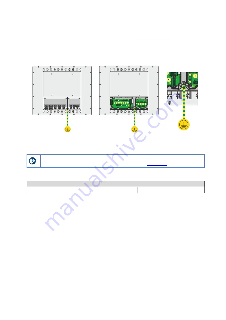
Grounding the device
Open the cover of the Ex i terminal box (see chapter
Ground the devices with a core cross section of at least 4 mm²
or in line with applicable
standards.
Using external earth connection:
8.5.4
Connecting data cable
Connect the data cables according to the terminal diagram (for copper connections) or
connect them to the sockets (for FO connections).
For detailed instructions see Installation Manual "IM_Mounting-Kit_xx8" on the CD /
DVD / USB stick included in the delivery or online under
8.5.5
Mounting the cover of the terminal boxes
Tightening torque
Terminal box cover screws
1 Nm to 1.5 Nm
8.5.6
Connecting associated equipment
The cover of the terminal boxes (Ex i / Ex e / Ex nA) includes mounting options for associated
equipment such as cable glands, cable connectors, buttons.
The associated equipment to be mounted inside the cover of the terminal boxes must meet the
following requirements:
Ingress protection:
IP66
Ex e terminal boxes:
IEC, ANSI/UL or CSA C22.2 number 60079-7
Ex i terminal boxes:
IEC, ANSI/UL or CSA C22.2 number 60079-11
Ex nA terminal boxes:
ANSI/UL or CSA C22.2 number 60079-15
Observe the specific requirements of the associated equipment used (e.g. permitted cable
diameter for cable glands, tightening torques, cable clamps).
Observe country-specific regulations, in particular any ambient parameters that may be
different (e.g. ambient temperature range).
In the case of AC devices, IEC 60950 stipulates that an easily accessible disconnection
mechanism must be located outside of the device which can be used to interrupt the power
supply.

