background image

225034 / 7570609300

2014-01-21·BA00·III·en·00

Mounting and Installation  

9

SolConeX Plug, 16 A

Series 7570/12

EN
EN
EN
EN
EN
EN
EN
EN
EN
EN
EN
EN
EN
EN
EN
EN
EN
EN
EN
EN
EN
EN
EN
EN
EN

7.2

Mounting / Dismounting, Operating Position

7.2.1 Assembly

Operating position

• Store in an unplugged state, suspended with the contacts pointing downward.

7.3

Installation

To prevent the plug pins from becoming dirty, use a suitable closing cover 

(see "Accessories and Spare Parts").

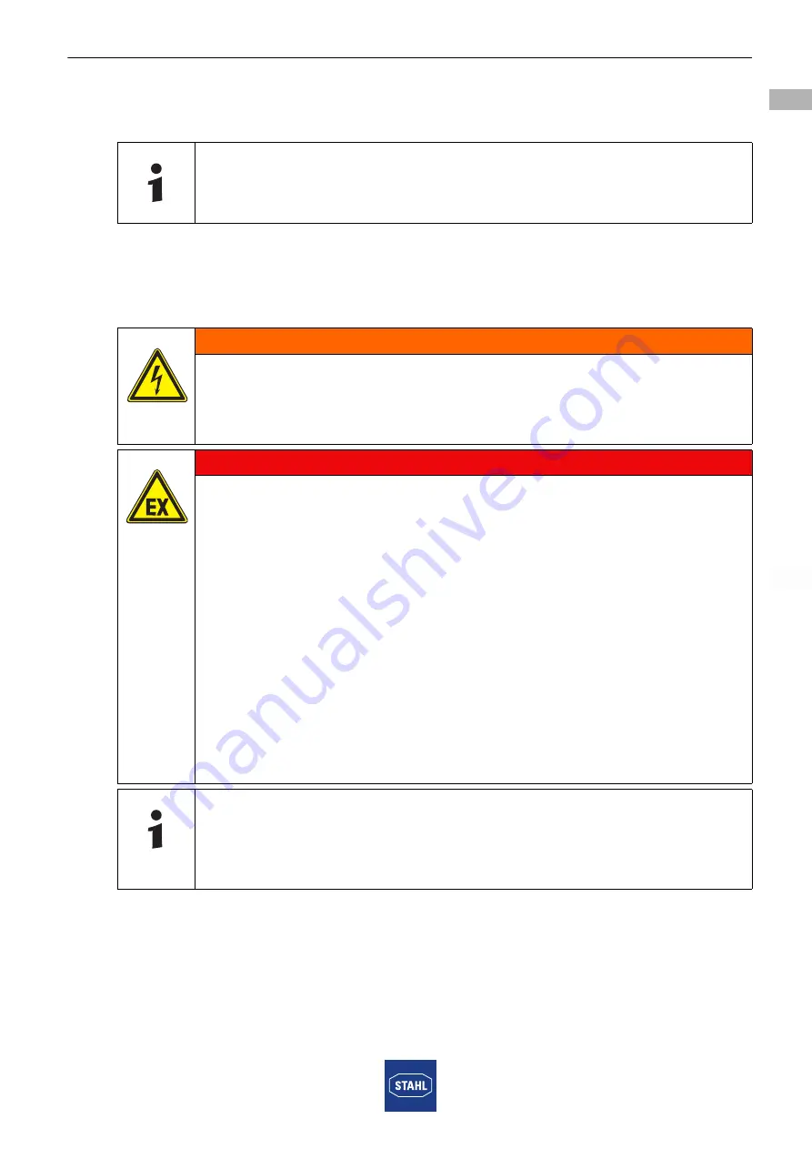
WARNING

Danger due to live components! 

Risk of severe injuries!

• Disconnect all connections and cables from the power supply.

• Secure the connections against unauthorized switching. 

DANGER

Risk of explosion! 

Risk of injuries and material damage!

• Select suitable cables to ensure that the maximum permissible 

conductor temperatures are not exceeded.

• When using the core end sleeves, attach them using a suitable 

tool.

• Observe the insulation capability and separation distances 

between intrinsically safe and non-intrinsically safe circuits 

according to EN 60079-14, section 12.

• Use only separately tested cable glands and stopping plugs with 

EC Type Examination Certificate.

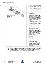
• The conductor insulation must reach to the terminal.

• Do not damage the conductor (e.g. nicking) when stripping it.

• Always connect the protective conductor.

Two conductors can be installed under one connection terminal. The material 

and conductor cross-section of both conductors must be identical. 

The conductors can be connected without any special preparations.

Summary of Contents for SolConeX 7570/12 Series

Page 1: ... EN DE EN DE EN DE EN DE EN DE EN DE EN DE EN DE Betriebsanleitung Operating instructions Additional languages www stahl ex com DE EN SolConeX Stecker 16 A SolConeX Plug 16 A Reihe 7570 12 Series 7570 12 ...

Page 2: ......

Page 3: ...DE DE DE DE DE DE DE DE DE DE DE DE DE DE DE DE DE DE DE DE DE DE DE DE DE Betriebsanleitung Additional languages www stahl ex com DE SolConeX Stecker 16 A Reihe 7570 12 ...

Page 4: ...inweise 4 2 3 Symbole am Gerät oder in Schaltplänen 4 3 Sicherheitshinweise 5 3 1 Aufbewahrung der Betriebsanleitung 5 3 2 Sichere Verwendung 5 3 3 Umbauten und Änderungen 5 4 Funktion und Geräteaufbau 5 4 1 Funktion 5 5 Technische Daten 6 6 Transport und Lagerung 6 7 Montage und Installation 7 7 1 Maßangaben Befestigungsmaße 7 7 2 Montage Demontage Gebrauchslage 9 7 3 Installation 9 8 Inbetriebna...

Page 5: ...snummer 2014 01 21 BA00 III de 00 Hardwareversion n a Softwareversion n a Die Originalbetriebsanleitung ist die englische Ausgabe Diese ist rechtsverbindlich in allen juristischen Angelegenheiten 1 3 Weitere Dokumente Datenblatt Data sheet 7570 Weitere Sprachen siehe www stahl ex com 1 4 Konformität zu Normen und Bestimmungen Siehe Zertifikate und EG Konformitätserklärung www stahl ex com 2 Erläut...

Page 6: ...m Gerät oder in Schaltplänen GEFAHR Gefahren für Personen Nichtbeachtung der Anweisung führt zu schweren oder tödlichen Verletzungen bei Personen WARNUNG Gefahren für Personen Nichtbeachtung der Anweisung kann zu schweren oder tödlichen Verletzungen bei Personen führen VORSICHT Gefahren für Personen Nichtbeachtung der Anweisung kann zu geringfügigen oder leichten Verletzungen bei Personen führen H...

Page 7: ...llation und im Betrieb die Angaben Kennwerte und Bemessungsbetriebsbedingungen auf Typ und Datenschildern sowie die Hinweisschilder am Gerät mit den Kabel und Leitungseinführungen beachten Bei Betriebsbedingungen die von den technischen Daten abweichen unbedingt bei der R STAHL Schaltgeräte GmbH rückfragen 3 3 Umbauten und Änderungen 4 Funktion und Geräteaufbau 4 1 Funktion Der Stecker 7570 12 ist...

Page 8: ...TEX 1013 E II 3 G Ex nA nC ia Ga IIC Gc E II 3 D Ex tc IIIC Dc Bescheinigungen und Zertifikate Bescheinigungen ATEX Technische Daten Elektrische Daten Bemessungs betriebsspannung max 690 V AC max 110 V DC Bemessungs betriebsstrom max 16 A Umgebungsbedingungen Umgebungs temperatur 30 55 C 50 C auf Anfrage Mechanische Daten Anzahl der Pole 2 P 3 P 3 P N Material Gehäuse Polyamid glasfaserverstärkt S...

Page 9: ...hrzeit Stellung Ansicht Vorderseite der Steckdose Anordnung der Kontaktstifte und Klemmenbezeichnungen Anordnung der Kontaktstifte und Klemmenbezeichnungen in der 6h Stellung Ansicht von der Vorderseite Maßzeichnung alle Maße in mm Zoll Änderungen vorbehalten 10337E00 Typ A B 7570 12 3 16 A 2 P 43 5 76 7570 12 4 16 A 3 P 49 89 7570 12 5 16 A 3 P N 56 5 92 7570 12 02395E00 Beispiel Uhrzeit Stellung...

Page 10: ...n 2 Frequenzen 100 Hz führen zu höherem Erwärmungsverhalten Dies muss durch max Umgebungs temperatur 40 C Temperaturklasse T5 oder Stromreduzierung auf 12 A kompensiert werden Polzahl Frequenz Hz Spannung V Kennfarbe Lage der Schutzkontaktbuchse 7570 3 2 P 50 und 60 100 130 gelb 4 h 50 und 60 200 250 blau 6 h 60 277 1 hellgrau 5 h 50 und 60 480 500 schwarz 7 h 300 500 2 50 grün 2 h DC 50 110 hellg...

Page 11: ...sionsgefahr Verletzungen und Sachschäden drohen Durch geeignete Leiterauswahl sicherstellen dass maximal zulässige Leitertemperaturen nicht überschritten werden Bei Verwendung von Aderendhülsen diese mit geeignetem Werkzeug aufbringen Isolationsvermögen und Trennabstände zwischen eigensicheren und nicht eigensicheren Stromkreisen gemäß EN 60079 14 Abschnitt 12 beachten Nur gesondert geprüfte und m...

Page 12: ... um 90 abschwenken Leitungen in entsprechende Klemmen einführen und festklemmen Anzugsdrehmoment siehe Kapitel Technische Daten Die abisolierten Leitungsenden müssen sich vollständig in der Klemme befinden Zugentlastung zurückschwenken und auf Leitung montieren Klemmstelle darf nicht unter Zug stehen Steckergehäuse festschrauben Anzugsdrehmoment siehe Kapitel Technische Daten Dichtung vorgestanzte...

Page 13: ... der Bajonettverschluss fest angezogen ist Kontrollieren ob die Oberfläche der Steckerstifte nicht beschädigt ist Nur in komplett montiertem Zustand betreiben 9 Betrieb Nach einem Kurzschluss im Stromkreis Funktionsfähigkeit des Steckers kontrollieren Der Stecker kann zusammen mit folgenden Produkten der Fa R STAHL betrieben werden Wandsteckdose 7570 11 und 7575 11 Flanschsteckdose 7570 15 und 757...

Page 14: ... lösbare Verbindungen z B Schrauben auf festen Sitz 10 2 Wartung WARNUNG Unbefugte Arbeiten am Gerät Gefahr von Verletzungen und Sachschäden Arbeiten am Gerät ausschließlich von dazu befugtem und entsprechend geschultem Personal ausführen lassen WARNUNG Gefahr durch spannungsführende Teile Schwerste Verletzungen möglich Alle Anschlüsse und Verdrahtungen spannungsfrei schalten Anschlüsse gegen unbe...

Page 15: ...sser oder milde nicht scheuernde nicht kratzende Reinigungsmittel verwenden Keine aggressiven Reinigungsmittel oder Lösungsmittel verwenden Eindringen von Wasser und Reinigungsmittel in die Kontaktbuchsen vermeiden 12 Entsorgung Nationale und lokal gültige Vorschriften und gesetzliche Bestimmungen zur Entsorgung beachten Materialien getrennt dem Recycling zuführen Umweltgerechte Entsorgung aller B...

Page 16: ...14 225034 7570609300 2014 01 21 BA00 III de 00 SolConeX Stecker 16 A Reihe 7570 12 ...

Page 17: ...EN EN EN EN EN EN EN EN EN EN EN EN EN EN EN EN EN EN EN EN EN EN EN EN EN Operating instructions Additional languages www stahl ex com EN SolConeX Plug 16 A Series 7570 12 ...

Page 18: ... 2 Warning Notes 4 2 3 Symbols on the Device or in the Circuit Diagrams 4 3 Safety Notes 5 3 1 Operating Instructions Storage 5 3 2 Safe Use 5 3 3 Modifications and Alterations 5 4 Function and Device Design 5 4 1 Function 5 5 Technical Data 6 6 Transport and Storage 6 7 Mounting and Installation 7 7 1 Dimensions Fastening Dimensions 7 7 2 Mounting Dismounting Operating Position 9 7 3 Installation...

Page 19: ...5034 7570609300 Publication Code 2014 01 21 BA00 III en 00 Hardware version n a Software version n a The original instructions are the English edition They are legally binding in all legal affairs 1 3 Further Documents Data sheet 7570 For further languages see www stahl ex com 1 4 Conformity with Standards and Regulations See certificates and EC Declaration of Conformity www stahl ex com 2 Explana...

Page 20: ...mage 2 3 Symbols on the Device or in the Circuit Diagrams DANGER Danger for persons Non compliance with the instruction results in severe or fatal injuries to persons WARNING Danger for persons Non compliance with the instruction can result in severe or fatal injuries to persons CAUTION Danger for persons Non compliance with the instruction can result in minor or light injuries to persons NOTICE A...

Page 21: ... installation and operation observe the information characteristic values and rated operating conditions on the rating and data plates and the information plates located on the device containing the cable glands Always consult with R STAHL Schaltgeräte in case of operating conditions which deviate from the technical data 3 3 Modifications and Alterations 4 Function and Device Design 4 1 Function T...

Page 22: ...5 ATEX 1013 E II 3 G Ex nA nC ia Ga IIC Gc E II 3 D Ex tc IIIC Dc Certifications and certificates Certificates ATEX Technical data Electrical data Rated operational voltage max 690 V AC max 110 V DC Rated operational current max 16 A Ambient conditions Ambient temperature 30 55 C 50 C on request Mechanical data Number of poles 2 P 3 P 3 P N Material Enclosure Polyamide glass fibre reinforced Degre...

Page 23: ...ock hour position View front side of the socket Arrangement of contact pins and terminal markings Arrangement of contact pins and terminal markings in the 6h position view from the front side Dimensional drawings all dimensions in mm inch Subject to alterations 10337E00 Type A B 7570 12 3 16 A 2 P 43 5 76 7570 12 4 16 A 3 P 49 89 7570 12 5 16 A 3 P N 56 5 92 7570 12 02395E00 Example clock hour pos...

Page 24: ...ons 2 Frequencies 100 Hz lead to increased heating This must be compensated by max ambient temperature 40 C temperature class T5 or current reduction to 12 A No of poles Frequency Hz Voltage V Colour code Position of earth contact sleeve 7570 3 2 P 50 and 60 100 130 yellow 4 h 50 and 60 200 250 blue 6 h 60 277 1 light grey 5 h 50 and 60 480 500 black 7 h 300 500 2 50 green 2 h DC 50 110 light grey...

Page 25: ...NGER Risk of explosion Risk of injuries and material damage Select suitable cables to ensure that the maximum permissible conductor temperatures are not exceeded When using the core end sleeves attach them using a suitable tool Observe the insulation capability and separation distances between intrinsically safe and non intrinsically safe circuits according to EN 60079 14 section 12 Use only separ...

Page 26: ... strain relief 7 and pivot it by 90 Insert the conductors into the corresponding terminals and clamp them for tightening torque refer to section Technical Data The stripped cable ends must be fully inside the terminal Pivot the strain relief back and mount it on the conductor The clamping point must not be under strain Screw down the connector enclosure for tightening torque refer to section Techn...

Page 27: ...observed Check whether the bayonet lock has been tightened firmly Make sure that the plug pin surface is not damaged Use only in completely mounted state 9 Operation Check the functionality of the plug after any short circuit in the electric circuit The plug can be used with the following products of R STAHL Wall mounting sockets 7570 11 and 7575 11 Flange sockets 7570 15 and 8571 15 The plug can ...

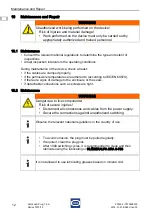
Page 28: ...ls if detachable connections such as screws are tight 10 2 Maintenance WARNING Unauthorized work being performed on the device Risk of injuries and material damage Work performed on the device must only be carried out by appropriately authorized and trained personnel WARNING Danger due to live components Risk of severe injuries Disconnect all connections and cables from the power supply Secure the...

Page 29: ...with a damp cloth use water or mild non abrasive non scratching cleaning agents Do not use aggressive detergents or solvents Prevent water and cleaning agents from penetrating the socket contacts 12 Disposal Observe national and local regulations and statutory regulation regarding disposal Separate materials when sending it for recycling Ensure environmentally friendly disposal of all components a...

Page 30: ...14 225034 7570609300 2014 01 21 BA00 III en 00 SolConeX Plug 16 A Series 7570 12 ...

Page 31: ......

Page 32: ...225034 7570609300 2014 01 21 BA00 III de en 00 ...

Page 33: ......

Reviews: