background image

Transport and Storage

4

209880 / 8581616300

2014-10-10·IO00·III·en·03

SolConeX Receptacle & Plug 125 A
8581/41 & 8581/22

7

Transport and Storage

Transport and storage are only permitted in the original packing.

8

Receptacle Installation

8.1 Enclosure mounting

Securely mount the receptacle in a vertical position as illustrated, 

using three 3/8

 (10 mm) screws and suitable washers. Mounting dimensions 

are marked on the back of the receptacle housing.

8.2 Conduit/Cable installation

For conduit installation, connect 2

 NPT conduit to the hub and avoid misalignment. 

For cable installation, connect a listed 2

 cable fitting to the hub. Conduit/cable fitting 

should not be tightened more than 100 ft-lbs (136 Nm) of torque.

8.3 Auxiliary contact

When using the 6 A rated early break and late make auxiliary contact 

for an electrical interlock or other control signal, connect 12 AWG copper wire to 

terminals 13 and 14. Torque the terminal screws to 3.54 in-lbs (0.4 Nm).

8.4 Function label

Remove the plastic function label (taped inside the cover), mark as required, remove 
backing strip and apply to the recessed area above the switch. Close the cover and 
tighten the cover screws.

Certificates

NEC / CEC

FM File No. 0R6A2.AX

IECEx

IECEx PTB 06.0034

ATEX

PTB 01 ATEX 1161

Ambient temperature

see explosion protection data -45 C° on request (internal lubrication using silicone grease)

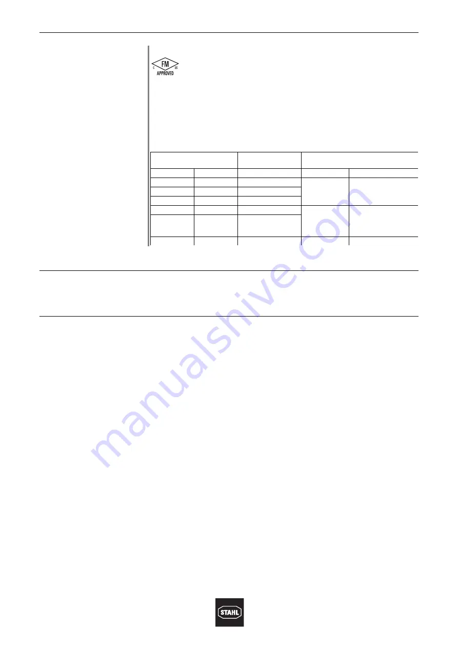
Assignment of temperature class / ambient temperature / rated operational voltage / rated 
connection cross-section

Valid for

 the following versions

: 209879_V03

Temperature class

Rated operational 
current

Rated connection cross-section

T6

T5

Socket

Plug

(

 + 45 °C

125 A

70 mm

2

50 mm

2

(

 + 40 °C

(

 + 55 °C

110 A

(

 + 45 °C

(

 + 60 °C

100 A

(

 + 40 °C

125 A

50  to 70 mm

2

35 mm

Use only heat-resistant 
cables 

)

 85 °C, e.g., 

Type NSSHÖU!

(

 + 45 °C

115 A

(

 + 40 °C

(

 + 55 °C

100 A

50  to 70 mm

2

35 mm

2

Summary of Contents for SolConeX 8581/41

Page 1: ...Installation Operating Maintenance Sheet SolConeX Receptacle Plug 125 A 8581 41 8581 22 ...

Page 2: ... IO00 III en 03 Subject to alterations 2 3 Disclaimer The nature of these instructions is only informative and does not cover all of the details variations or combinations in which this equipment may be used stored delivered installed safely operated and maintained Since conditions of use of the product are outside of the care custody and control of the manufacturer the purchaser should determine ...

Page 3: ...s The receptacle is suitable for use on a circuit capable of delivering not more than 10 000 rms symmetrical amperes 600 V maximum when protected by properly sized Class J fuses 200 amperes maximum Supply wires shall be rated for 75 C 5 Conformity to Standards The 8581 41 Series of receptacles and the 8581 22 Series of plugs have multiple certifications printed on the nameplate 6 Technical Data Pl...

Page 4: ...tact for an electrical interlock or other control signal connect 12 AWG copper wire to terminals 13 and 14 Torque the terminal screws to 3 54 in lbs 0 4 Nm 8 4 Function label Remove the plastic function label taped inside the cover mark as required remove backing strip and apply to the recessed area above the switch Close the cover and tighten the cover screws Certificates NEC CEC FM File No 0R6A2...

Page 5: ...markings on the plug Torque all terminal screws to 221 265 in lbs 25 30 Nm including all unused terminals 10 Plug Wiring 14966E00 Figure 1 10 1 Cord type Select a flexible cord with copper conductors of the appropriate insulation ampacity and 90 C temperature rating For installations in the U S refer to the National Electrical Code Articles 400 4 400 5A 400 5B 501 11 502 12 and 503 10 For installa...

Page 6: ...from the end 10 6 Connection to terminals Open the strain relief clamp screws and flip the clamp to the side Attach the leads to the appropriate terminals Terminal markings correspond to receptacle terminal markings 10 7 Strain relief Flip back the strain relief clamp remove clamp s plastic inserts if necessary to fit the outer diameter of the cord Make sure that the remaining plastic inserts have...

Page 7: ...12 Maintenance These receptacles require no maintenance other than a periodic inspection for damage and proper operation Any damaged equipment should be replaced promptly to ensure the electrical safety and explosion protection of the system 13 Disposal The national and local waste disposal regulations have to be observed WARNING Observe the labels on the receptacle and plug with regard to the use...

Page 8: ...8 209880 8581616300 2014 10 10 IO00 III en 03 SolConeX Receptacle Plug 125 A 8581 41 8581 22 ...

Reviews: