S
TEX
Z
1.FM
08.11
33
Kettenzüge STex, Zone 1, 21
STex Chain Hoists, Zone 1, 21
Palans à chaîne STex, zone 1, 21
Technische Daten
Technical Data
Caractéristiques techniques
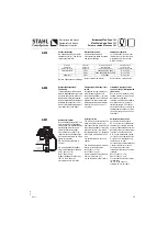
Max. cable length
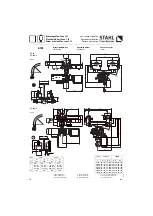
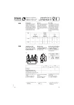
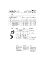
Wheel loads
R1, R2
=
Wheel pair load
(without impact and
compensating factors)
Q (kg)
=
Working load + dead load
Go (kg) =
Total weight see page 8
(hoist + trolley)
Longueur du câble maxi.
Réaction par galets
Formel/Formula/Formule:
R1, R2
=
Réaction par paire de galets
(sans facteur l'effort ni
coefficient
compensateur)
Q (kg)
=
Charge d’utili poids
mort
Go (kg) =
Poids total voir page 8
(palan + chariot)
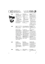
R1
max
= Q x (a1-a2) + 0,6 x Go
a1
R2
max
= Q x a2 + 0,4 x Go
a1
Max. Leitungslänge
Radlasten
R1, R2
=
Radpaarbelastung (ohne
Stoß- und Ausgleichzahl)
Q (kg)
=
Tragfäh Totlast
Go (kg) =
Gesamtgewicht siehe Seite 8
(Ket Fahrwerk)
Typ
Type
Tragfähigkeit
Working load
Charge d’utilisation
R1
R2
a1
a2
[kg]
[kN]
[kN]
[mm]
[mm]
ST 20 1/1
250
500
1000
2,67
3,95
6,20
2,19
3,45
5,77
144
72
ST 20 2/1
1000
1600
2000
6,41
9,20
11,16
5,91
8,75
10,71
ST 50 1/1
2000
2500
11,29
13,73
10,88
13,34
199
100
ST 50 2/1
3200
5000
17,21
25,99
16,83
25,71
*
Zuordnung zu den Kettenzügen
siehe Seite 9
*1 Zuleitung stationäres Hubwerk, feste
Verlegung in Installationsrohr - PVC
*2 Fahrwerk, Zuleitung bis Einspeisepunkt,
feste Verlegung in Installationsrohr -
PVC
*3 Fahrwerk, flexible Gummileitung ent-
lang der Laufbahn, Leitungsgirlande frei
in der Luft
*4 S = Mindestquerschnitt
L1-L3 = max. Zuleitungslänge der
einzelnen Stromzuführungsarten.
Summe der Spannungsabfälle
<
5%.
Bei größeren Leitungsquerschnitten
errechnen sich die max. Leitungsquer-
schnitte wie folgt: L* = L x S* / S
*
Assignment to chain hoists:
see table page 9
*1 Supply to stationary hoist, fixed
installation in PVC conduit
*2 Trolley, supply up to feed point, fixed
installation in PVC conduit
*3 Trolley, flexible rubber-sheathed cable
along runway, festoon cable in free air
*4 S = minimum cross-section
L1-L3 = max. length of supply cable with
different types of power supply.
Sum of voltage drops
<
5%.
In the case of larger cross-sections, the
max. cable cross-sections are
calculated as follows: L* = L x S* / S
*
Affectation aux palans à chaîne, voir
page 9
*1 Ligne d'alimentation, palan à poste fixe,
posée à demeure dans tube d'installa
tion - PVC
*2 Chariot, ligne d'alimentation allant
jusqu'au point d'alimentation, posée à
demeure dans tube d'installation - PVC
*3 Chariot, câble sous caoutchouc le long
de la voie de roulement, câble aérien en
forme de guir-lande
*4 S = Section minimale
L1-L3 = Longueur maximale de la ligne
d'alimentation des différents types
d'alimentation élec-trique.
Somme des chutes de tension
<
5%
Avec de plus fortes sections de câble,
la section max. de câble se calcule
comme suit : L* = L × S* / S
C080
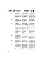
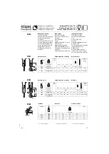
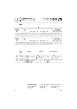
Max. Leitungslänge L1, L2 und L3 bei Schützsteuerung und Leitungsquerschnitt S
Max. cable length L1, L2 and L3 with contactor control and cross section S
Longueur du câble maxi. L1, L2 et L3 avec commande par contacteurs et section S
Hubmotor Type
Hoist motor type
Type de moteur de
levage
*
Kabelstromzuführung für
Festoon power supply for
Alimentation électrique par câble pour
Spannungsabfall
Voltage drop
Chute de tension
*4
50 Hz
60 Hz
230 V
400 V
500 V
400 V
460 V
575 V
2/8A05ex
S [mm²]
1,5
1,5
1,5
1,5
1,5
1,5
Stationär / Stationary / Fixe accroché *1
∆
U<5%
L1 [m]
73
224
348
167
221
342
Steigleitung / Rising main / Colonne montante *2
∆
U<1%
L2 [m]
15
45
70
33
44
68
Fahrwerk / Trolley / Chariot *3
∆
U<4%
L3 [m]
59
179
279
134
177
273
2/12A1ex
S [mm²]
2,5
1,5
1,5
1,5
1,5
1,5
Stationär / Stationary / Fixe accroché *1
∆
U<5%
L1 [m]
35
64
100
52
69
107
Steigleitung / Rising main / Colonne montante *2
∆
U<1%
L2 [m]
7
13
20
10
14
21
Fahrwerk / Trolley / Chariot *3
∆
U<4%
L3 [m]
28
51
80
41
55
85
2/12A2ex
S [mm²]
2,5
1,5
1,5
2,5
2,5
1,5
Stationär / Stationary / Fixe accroché *1
∆
U<5%
L1 [m]
22
39
61
48
63
59
Steigleitung / Rising main / Colonne montante *2
∆
U<1%
L2 [m]
4
8
12
10
13
12
Fahrwerk / Trolley / Chariot *3
∆
U<4%
L3 [m]
17
31
49
38
51
47
C090

