Need the Owner's Manual for your Stairmaster FreeRunner 5400 ESS? Look no further! Download the manual for free from our website and get all the information you need to make the most of your workout.
Page 1: ...FreeRunner 5400 SS Owner s Manual ...
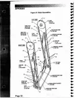
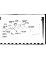
Page 2: ...R HEEL LINK CHAIN 40 12 5 PN 21866 DETAIL A STRIDE SENSOR PN 25112 HEEL LINK PILLOW BLOCK BEARING PN 21941 POWER CONTROL BOARD PN 25102 PEDAL RETURN SPRING IPN 21093 CHAIN LINK 30 25 PN 22740 05 UPPER FRONT DRIVE CHAIN 40 24 5 PN 21826 STEP CHAIN 40 47 5 PN 21906 HEEL LINK TURNBUCKLE ASSY PN 21852 MOUNTING BLOCK LOWER REAR DRIVE LEFT PN 25304 CHAIN 40 64S PN 21823 Figure 19 Final Assembly left Sid...
Page 3: ...IN 40 24 5 IPN 21826 DRIVE CHAIN TURNBUCKLE ASSY IPN 21852 MOUNTING BLOCK r J RIGHT pN 25303 BUMPER IPN 284961 LOWER REAR DRIVE CHAIN 40 64 5 IPN 218231 APPENDIX Page 71 HEEl LINK TURNBUCKLE ASSY IPN 21852 DETAIL A Figure 20 Final Assembly Right Side CHAIN LINK 15 900 IPN 22738 05 HEEl LINK CHAIN 40 5 5 _____ IPN 20532 EXTENSION SPRING IPN 219261 LOWER HEEl LINK CHAIN 40 12 5 SEEFIGURE21 IPN 21866...
Page 4: ...PPER HEEl LINK CHAIN 2XPN 2190S 3 r CHAINLINK IS 900 1XPN 22738 oS RIGHT SIDE TURNBUCKLE ASSEMBLY 3XPN 218S2 2 SPRING 2XPH 22752 STEP CHAIN 2X21906 CHAINUNK 30 25 2XPH 22740 D5 LOWER REAR DRIVE CHAIN lXPN21907 SPRING CHAIN CONNECTOR 8 2XPN 2D768 SPRING CARTRIDGE ASSEMBLY 1XPN 22694 CHAIN 14D 12 S 3 4XPH 21866 evLDWER FRDNT DRIVE CHAIN 1XPH 21823 Page 72 APPENDIX ...
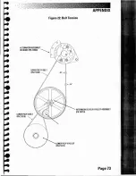
Page 5: ...APPENDIX Page 73 1 I i 1 J INTERMEDIATE POLY V PULLEY ASSEMBLY IPN 25216 Figure 22 Belt Tension ALTERNATOR ASSEMBLY WI BRAKE IPN 226661 LOWER POLY V BELT PN 218181 ...
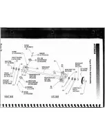
Page 6: ...N 25304 ORIVE SHAFT IPN 227111 I 10 WASHER 12 XPN 22222 r HEEL LINK _ IDLER SPROCKET 12 XPN 25249 1 SCREW 12 XPN 25211 MOUNTING BLOCK RIGHT SIDE r IPN25303 ffi DRIVE CHAIN IDLER SPROCKET II 4 X PN 22640 WASHER I 2 X23739 SCREW 2 X PN 25208 SCREW 12 XPN 28233 j RIGHT SIDE THRUST BEARING 14 XPN 201981 SNAP RING 2 XPN 20206 J r 2 0 THRUST J WASHERS 8 XPN 20197 SPROCKET ASSEMBLY 2 XPN 10382 11 a I ...
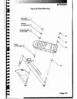
Page 7: ...T KEY PN 22758 e3 MOUNTING SCREWS 4 XPN 22204 BEARING BLOCK ASSEMBLY SET SCREW PN 25197 PN 22037 o r 0 O 0 LEG SPROCKET PN 21816 03 OJ WASHER PN 22709 05 SPLIT LOCK WASHER 2 XPN 23729 FLAT WASHER 12 XPN 25253 WASHER SPLIT LOCK PN 25181 PILLOW BLOCK BEARING r1 lPN 25247 r SCREW JAM NUT 2 XPN 25256 PN 22708 tJ C Q CD J I ...
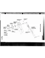
Page 8: ...ST WASHER 14 XPN 25186 HEEL PIVOT PN 22672 LEFT PN 22673 RIGHT BEARING BLOCK ASSEMBLY WASHER SPLIT LOCK I HEEL PIVOT PN 251 81 SPROCKET p A 18 PN21892 05 PILLOW BLOCK BEARING i c IPN 245461 f c IV cfJcfJ SCREW JAM NUT 2 XPN 25256 PN 21932 SPLIT LOCK WASHER MOUNTING SCREWS WASHER PN 21933 4 XPN 22204 2 XPN 23729 FLAT WASHER 2 XPN 25253 a Q Q CD 0 ...
Page 9: ...APPENDIX Page 77 3 2 4 l I I 1 I M I I Y J I I J i o 1 I I I I II Figure 26 Pedal Mounting WASHER 2 XPN2187l 2 SNAP RING 2 XPN 20213 1 THRUST WASHER 3 2 XPN 21937 SPACER 2 XPN 2528610 ...
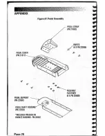
Page 10: ...6 PEDAL STRAP PN 21862 o e c o 0 PUSHNUT FASTENER 6 XPN 20508 Figure 21 Pedal Assembly PEDAL COVER PN 21817 PEDAL SHAFT OUSING PN 22692 INCLUDES PRESSED IN BRONZE BUSHING PN 20002 APPENDIX PEDAL SUPPORT PN 22690 Pane 78 ...
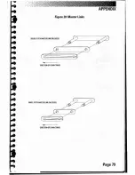
Page 11: ...Page 79 APPENDIX Figure 28 Master Links DIRECTION OF CHAIN TRAVEl DIRECTION OF CHAIN TRAVEL DOUBLE PITCH MASTER LINK IPN 20329 SINGLE PITCH MASTER LINK IPN 25305 ...
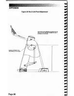
Page 12: ...KLE TO ADJUST THE TOP EDGE OF THE HEEl LINK PIVOT ASSEMBLY SO THAT IT IS PARAUEL TO THE FLOOR _ W i I V P i j to i Ji t i Figure 29 Heel Link Pivot Adjustment lo V o I t y j tl I I 1 Yo I ALIGN THE TOP EDGE OF THE PIVOT PARALLEL TO THE FLOOR Page 80 ...
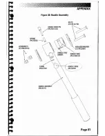
Page 13: ...Figure 30 Handle Assembly APPENDIX Page 81 SHOULDER WASHER 2 XPN 22681 BOLTS 2 XPN 22718 SPRING PN 25250 HANDLE KNOB PIN IP 25251 051 HANDLE ASSEMBLY PN 25217 ACORN NUTS 2 XPN 22716 tc ...
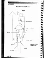
Page 14: ...CH ASSEMBLY PN 27002 I I 0 to 00 ItII v I 00 fw t S i y t I 1 GREEN WIRE RED WIRE 4 iI BRAKE ON SWITCW o 0 _ _ BRAKE OFF SWITCW Figure 31 Limit Switch Assemblv BLACK WIRE o BRAKE ACTUATOR ARM IPN 22791 05 APPENDIX BRAKE CAM IPN 21840 Page 82 ...
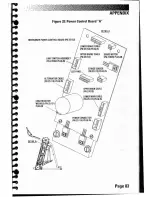
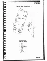
Page 15: ...L A i I I p V II III Y I lil i t I I 2 A I I 1 1 1 nl Page 83 Figure 32 Power Control Board I AU LIMIT SWITCH ASSEMBLY PN 27002 PlUG IN LOAD RESISTOR W CABLE pN 25121 PLUG IN FREERUNNER POWER CONTROL BOARD IPN 25102 ...
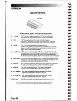
Page 16: ... Start at intensity level 1 on the console and continue through level 20 The LED will fade out as you increase intensity If the LED does not function properly chock the main cable and power control board 5 Stride Sens r OW when the pedals are aligned If OFF ensure that the pedals are aligned and chock the stride sensor magnet position see page 63 Also chock the stride sensor board stride sensor ca...
Page 17: ... III Y I to to iN i Y I 1 t I APPENDIX Page 85 CONSOLE PLUG IN On the PCB Board Pin 1 Alt Off Pin 2 VSupply Pin 3 B Scaled Pin 4 Resistor Control Pin 5 VCC Pin 6 N C Pin 7 Tach Pin 8 N C Pin 9 Stride Sensor Pin 10 Ground 1 RII t JII j i P Wl tiJf I S L I 1 to if J ...
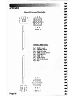
Page 18: ...t Off Pin 3 RED B Scaled Pin 4 ORG Resistor Control Pin 5 YELLOW vee Pin 6 GRN Ta h Pin 7 BLU Grouoo Pin 8 VIO Stride Sensor Ping NIt 1 2 3 CONSOLE MAIN CABLE Figure 35 Console Main Cable L J 3 2 1 000 6 000 4 000 r l 987 VIEW A A Page 86 APPENDIX ...
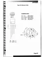
Page 19: ...APPENDIX Page 87 4 ALTERNATOR CABLE Pin 1 Bt White ire Pin 2 Ground Black WI e Pin 3 Field Brown YVlre Pin 4 Tach Blue Wire DIODE Figure 36 Alternator Cable A J II VIEW A A 1 2 4 9J 9J A L ...
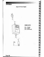
Page 20: ...Pin 1 VSupply Pin 2 Ground Pin 3 Earth Ground POWER SUPPLY Figure 37 Power Supply Pins 1 2 3 t APPENDIX Pane 88 ...
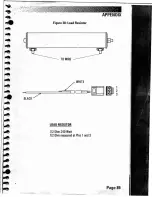
Page 21: ... v I I I V I 0 I 0 I l t I 0 to WHITE APPENDIX Page 89 TO WIRE Figure 38 load Resistor LOAD RESISTOR 1 2 Ohm 240 Watt 1 2 Ohm measured at Pins 1and 3 BLACK ...