Page 16
STRATUS SYSTEMS CONSOLE
EXERCISE PROGRAM KEYPAD
The purple exercise keypad is located below the display and to the left of the
function keypad. While the console is in the ATTRACT mode, press one of the
exercise program keys to preview the desired workout.
The sequence of prompts for the preset exercise programs is slightly
different than the sequence described earlier for the MANUAL program. After
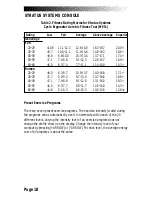
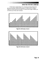
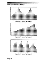
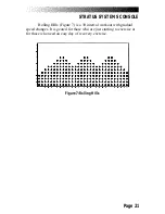
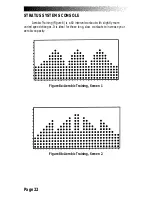
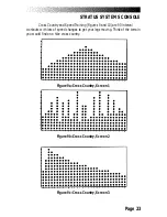
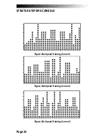
you press one of the exercise program keys, the exercise program profile is
scrolled across the display.
After the profile is scrolled, the prompts are:
•
“
PRESS ENTER KEY TO SELECT
”
•
“
ENTER BODY WEIGHT
” -- type in your body weight in
pounds (or kilograms if your console is set to metric units).
•
“
ENTER LEVEL 1 - 20
” -- select your intensity level with
level 1 being the easiest and level 20 the hardest.
•
“
ENTER TIME 5 - 60
” -- select the workout duration in one
minute increments from five to 60.
The Quick Start Option
You can begin a manually-paced workout without pressing any keys just by
pedaling for 15 seconds. This program will last for 15 minutes.
You can quickly start a preset workout by first pressing one of the
purple exercise program keys and then pressing [ENTER] twice. You do not have
to enter any other information. The length of the workout is set automatically
and varies with the program. Quick starting MANUAL gives you a 15 minute
workout. The preset workouts last five minutes for every thirty intervals. So, a 60
interval program will last 10 minutes. The workout stats available are time,
speed, distance, watts, level, calories, RPM, and pulse (if wearing a transmitter).
The Fit Test does not have a quick start option.
Summary of Contents for STRATUS 3300 CE
Page 1: ...Stratus Systems Owner s Manual...
Page 66: ...Page 59 FIGURES Figure 11 Cover Fasteners...
Page 67: ...Page 60 FIGURES Figure 12 Cover Fastener Locations 3300 CE...
Page 68: ...Page 61 FIGURES Figure 13 Cover Fastener Location 3900 RC...
Page 69: ...Page 62 Figure 14 Right Side View 3300 CE FIGURES...
Page 70: ...Page 63 Figure 15 Left Side View 3300 CE FIGURES...
Page 71: ...Page 64 FIGURES Figure 16 Right Side View 3900 RC...
Page 72: ...Page 65 FIGURES Figure 17 Left Side View 3900 RC...
Page 73: ...Page 66 FIGURES Figure 18 Seat Adjustment Pin Assembly 3300 CE...
Page 74: ...Page 67 FIGURES Figure 19 Seat Assembly 3900 RC...
Page 75: ...Page 68 FIGURES Figure 20 Drive Chain Tension...
Page 76: ...Page 69 FIGURES Figure 21 Intermediate Shaft Assembly...
Page 77: ...Page 70 FIGURES Figure 22 J Bolt Assembly...
Page 78: ...Page 71 FIGURES Figure 23 Crank Assembly...
Page 79: ...Page 72 FIGURES Figure 24 Alternator Flywheel Assembly...


