Page 48
SEAT LOCATION POST (3300 CE ONLY)
1.
Pull the seat adjustment knob out and raise the seat.
2.
Insert a phillips screwdriver into one of the holes in the seat post that
are visible above the seat tube cap (see Figure 18). Gently lower the
seat so that the seat is held up by the screwdriver.
3.
Hold the seat adjustment shaft with a pair of locking pliers and
remove the seat adjustment knob from the shaft by turning the knob
counterclockwise.
4.
Remove the screwdriver from the hole in the seat post and lower
the seat slightly so the seat adjustment shaft engages a hole in the
seat post.
5.
Remove the internal snap ring that is now visible inside the seat
knob housing.
6.
Lift the seat slightly and pull out the seat adjustment shaft. Remove
both washers and the spring from inside the seat knob housing.
7.
Insert a phillips screwdriver into one of the holes in the seat post that
are visible above the seat tube cap and remove the internal snap
ring located in front of the seat adjustment bushing inside the seat
knob housing.
8.
Remove the two screws securing the seat tube cap to the frame.
9.
Remove the screwdriver from the seat post. Raise the seat tube cap
up and away from the frame.
PARTS REMOVAL AND REPLACEMENT
TO REDUCE THE RISK OF EYE INJURY, WEAR EYE
PROTECTION WHEN REMOVING SNAP RINGS.
!
WARNING
Summary of Contents for STRATUS 3300 CE
Page 1: ...Stratus Systems Owner s Manual...
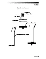
Page 66: ...Page 59 FIGURES Figure 11 Cover Fasteners...
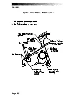
Page 67: ...Page 60 FIGURES Figure 12 Cover Fastener Locations 3300 CE...
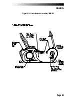
Page 68: ...Page 61 FIGURES Figure 13 Cover Fastener Location 3900 RC...
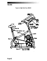
Page 69: ...Page 62 Figure 14 Right Side View 3300 CE FIGURES...
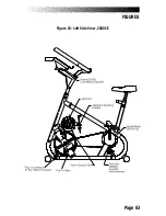
Page 70: ...Page 63 Figure 15 Left Side View 3300 CE FIGURES...
Page 71: ...Page 64 FIGURES Figure 16 Right Side View 3900 RC...
Page 72: ...Page 65 FIGURES Figure 17 Left Side View 3900 RC...
Page 73: ...Page 66 FIGURES Figure 18 Seat Adjustment Pin Assembly 3300 CE...
Page 74: ...Page 67 FIGURES Figure 19 Seat Assembly 3900 RC...
Page 75: ...Page 68 FIGURES Figure 20 Drive Chain Tension...
Page 76: ...Page 69 FIGURES Figure 21 Intermediate Shaft Assembly...
Page 77: ...Page 70 FIGURES Figure 22 J Bolt Assembly...
Page 78: ...Page 71 FIGURES Figure 23 Crank Assembly...
Page 79: ...Page 72 FIGURES Figure 24 Alternator Flywheel Assembly...

