Page 51
PARTS REMOVAL AND REPLACEMENT
10.
Inspect the freewheel for smoothness of operation in the counter
clockwise direction and for positive engagement in the clockwise
direction. Use a freewheel tool to remove the freewheel from the
Poly-V pulley, if replacement is necessary.
11.
Reverse the steps to reinstall the parts. Additionally, ensure that:
•
The short side of the J-bolt hook faces to the rear of the frame.
•
The wider portion of the threaded spacer faces to the right.
•
The drive chain is adjusted according to the procedure outlined
in the “Drive Chain” section of this manual.
•
The Poly-V belt is adjusted so the distance between the edges of
the top and bottom spring retainers on the J-bolt is 1-11/16"
(4.3 cm) (see Figure 22).
PEDALS
1.
Use a 15-mm pedal wrench or a 5/8" open end wrench to loosen and
remove the pedals from the crank.
2.
The pedal on the left side of the crank is marked with an "L" on the
pedal spindle, and has reverse threads. Turn the wrench on the left
pedal clockwise to loosen it. Turn the wrench on the right pedal
clockwise to tighten it.
3.
Apply a small amount of multi-purpose grease to the threads of the
pedal spindle before reinstalling the pedals on the crank.
CRANK AND BOTTOM BRACKET ASSEMBLY
1.
Remove both neck covers (3300 CE only) and the side covers.
2.
Remove the drive chain.
3.
Remove the left pedal.
Summary of Contents for STRATUS 3300 CE
Page 1: ...Stratus Systems Owner s Manual...
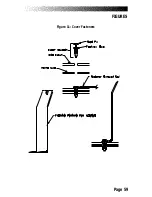
Page 66: ...Page 59 FIGURES Figure 11 Cover Fasteners...
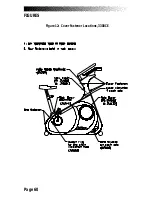
Page 67: ...Page 60 FIGURES Figure 12 Cover Fastener Locations 3300 CE...
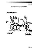
Page 68: ...Page 61 FIGURES Figure 13 Cover Fastener Location 3900 RC...
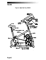
Page 69: ...Page 62 Figure 14 Right Side View 3300 CE FIGURES...
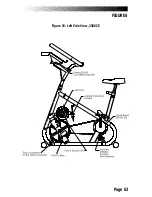
Page 70: ...Page 63 Figure 15 Left Side View 3300 CE FIGURES...
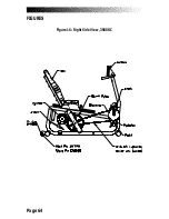
Page 71: ...Page 64 FIGURES Figure 16 Right Side View 3900 RC...
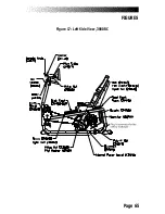
Page 72: ...Page 65 FIGURES Figure 17 Left Side View 3900 RC...
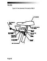
Page 73: ...Page 66 FIGURES Figure 18 Seat Adjustment Pin Assembly 3300 CE...
Page 74: ...Page 67 FIGURES Figure 19 Seat Assembly 3900 RC...
Page 75: ...Page 68 FIGURES Figure 20 Drive Chain Tension...
Page 76: ...Page 69 FIGURES Figure 21 Intermediate Shaft Assembly...
Page 77: ...Page 70 FIGURES Figure 22 J Bolt Assembly...
Page 78: ...Page 71 FIGURES Figure 23 Crank Assembly...
Page 79: ...Page 72 FIGURES Figure 24 Alternator Flywheel Assembly...

