background image

15

2

27/04/2022  Rev:1.0.0 

English

WARNING: the electrical connection must be carried out 

ONLY by qualified personnel.

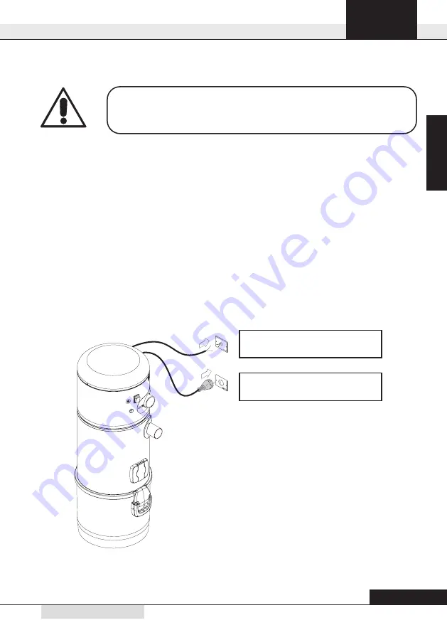
Micro Line / Suction socket 

12V

Power supply  AC 230V

6.5 Electrical connection

Before connecting the system to the electrical power supply check that the supply voltage corresponds 
to the one required by the vacuum cleaner (see the identification plate). 
The manufacturer declines any responsibility for damages to people and/or objects due to the connec

-

tion to a non-complying electric wiring.

Follow the instructions (see picture) detailed below to carry out the operation: 

•  Connect the input signal cable (MICRO LINE) to the suction sockets. 
•  Insert the plug of the power supply cable from the central system in the electric socket. 
•  Check that the electrical wiring of the house has been set up in compliance with the electrical regula

-

tions in force. 

•  Do not power the system with supply voltage from provisional or temporary switchboards (for example 

construction sites switchboards) to avoid possible damage to the electronic parts.

Summary of Contents for Vacu PRO

Page 1: ...ENG Installation Use and Maintenance Instructions Central Vacuum Unit Vacu PRO ...

Page 2: ......

Page 3: ...ble closure guards safety 8 4 7 Identification plate 9 5 PACKAGE CONTENTS 10 6 INSTALLATION 11 6 1 Preliminary operations 11 6 2 Place of installation 11 6 3 Fixing the vacuum cleaner to the wall 12 6 4 Connection to the piping network 13 6 5 Electrical connection 15 6 6 Using the service socket 16 7 MAINTENANCE 16 7 1 Programmed routine maintenance 16 7 2 Cleaning the suction container cylinder 1...

Page 4: ...o VACU PRO 2330 2340 Suction coupling Ø mm 50 50 Air exhaust Ø mm 50 50 IP Protection Degree IP 20 20 Power supply V ac 220 230 220 230 Frequency Hz 50 60 50 60 Motor power kW 1 8 1 9 Absorption A 7 9 8 2 Socket power supply V dc 12 12 Maximum air flow m3 h 240 257 Dust bin capacity l 25 25 Air venting YES YES Air exhaust silencer YES YES Weight kg 10 5 10 5 Sound level dB A 70 346 120 112 177 153...

Page 5: ...5 2 27 04 2022 Rev 1 0 0 English Main switch Thermal switch Air exhaust ON OFF switch service inlet Service vacum inlet Closing handle and hook Dust bin Dust inlet 1 2 3 4 6 7 8 5 ...

Page 6: ...Do not suction cement flour or similar materials including the construction site dust lime remains plaster powder and so on which may cause the reduction of the vacuumed air with a consequent da mage of the motor The system has not been designed to be used in environments with risk of explosion and the refore it is forbidden to vacuum clean materials with high explosion risk gunpowder or materials...

Page 7: ...on Children should not play with the ma chine nor with the suction sockets This equipment should not be used by people including children with reduced psychic sensory or mental capacities or by people with no experience nor knowledge of the system unless they are under the guidance or instructed to use the machine by people responsible for their safety Children must always be supervised to ensure ...

Page 8: ...als and during the manufacturing cycles of our products their presence in p p m parts per million cannot be completely excluded due to micro pollution of raw materials 4 5 Fixed closure guards safety The vacuum cleaner is delivered to the Customer with its main body completely assembled Moving parts suction motor turbine blades are protected by a protection grid directly assembled on the inlet of ...

Page 9: ...cation plate is assembled on the side of the connection to the piping network This should not be removed or damaged IP20 Model P N S N Manufacturer Identification Technical data of the electric motor Serial Number Type of Central vacuum cleaner Article CE conformity marking ...

Page 10: ... the accessory kit consisting of the following parts 1 N 1 wall mounting bracket for fixing the central vacuum unit to the wall 2 N 1 rubber sleeves for connection to the vacuum pipe network 3 N 3 metal clamps for fixing the sleeves 4 N 1 installation use and maintenance manual 5 N 1 plastic air exhaust silencer for air discharge 1 2 3 4 5 MANUALE TECNIC O S l ...

Page 11: ...uction piping network installed by qualified personnel who has already selected the most suitable location Below you will find the main indications to be followed for a correct installation If the appliance will be connected to a pipe network on more than one floor we suggest you to install it in the lowest part of the building Install the system in service rooms e g garage or storage room away fr...

Page 12: ...ht times the weight of the system itself The system should be positioned high enough off the ground to allow the dust collection bin to be emptied and the filter to be replaced in a simple way Position the system so as to keep a minimum distance of 60 cm around the appliance for extraordinary maintenance To do this follow the instructions detailed below 2 1 Drill the holes Tighten the screws in th...

Page 13: ...sleeve connect the dust inlet coupling of the cyclonic vacuum cleaner identified with C in the picture to the suction pipe from the piping network 3 By using the sleeve connect the air outlet of the central vacuum unit marked with D to the air outlet of the house 4 Glue the silencer E on the exhaust pipe near the exhaust air grid N B do not glue the pipe end of the network pipe to the dust inlet c...

Page 14: ...uld it be necessary to convey the air discharge to the outside please follow the following instructions Maximum length of the discharge pipe N B Diameter of the outlet pipe for a length up to 10 m 50 mm Exhaust pipe diameter for lengths over 10 m 63 mm ...

Page 15: ...mages to people and or objects due to the connec tion to a non complying electric wiring Follow the instructions see picture detailed below to carry out the operation Connect the input signal cable MICRO LINE to the suction sockets Insert the plug of the power supply cable from the central system in the electric socket Check that the electrical wiring of the house has been set up in compliance wit...

Page 16: ... entail damages Ensure the system s surface is completely dry before switching it back on Always use a suitable mask to protect against airborne dust and wear latex gloves to protect your hand skin BEFORE CARRYING OUT ANY MAINTENANCE OPERATION IT IS MANDATORY TO UNPLUG THE POWER SUPPLY CABLE FROM THE POWER SUPPLY INLET PROTECTIVE MASK AND GLOVES MUST ABSOLUTELY BE WORN Working time h Maintenance E...

Page 17: ... back in position 4 Reassemble the dust bin inside its housing under the suction system and lock the closing handles Switch the suction system on by pressing the ON OFF switch Remember to be careful when emptying the bin if there is a big quantity of dust make sure you do not throw away the conveyor cone Always check that the conveyor cone is still in place and correctly assembled in its housing i...

Page 18: ...or repairs and or maintenance which are not expressly authorized in this manual is absolutely forbidden Any repair for breakage or malfunctioning must be carried out by qualified Technical Assistance personnel Any intervention of non authorized personnel will result in the invalidation of any guarantee of the product and the manufacturer will not be held responsible for any eventual damage to pers...

Page 19: ...service suction socket is working Use only one suction inlet at a time The flexible hose or the cleaning accessories are broken Check the flexible hose and the accessories are not damaged change them if necessary The filter cartridge is dirty Clean the filter cartridge The sealing gasket of the dust bin is damaged Check sealing gasket integrity There is a clogging in the suction pipes of the pipe ...

Page 20: ...F0920620 36031 Dueville VI ITALIA Via Prati 11 Tel 39 0444 1803418 info stakorr it ...

Reviews: