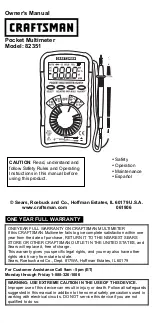
only figure
“
1
”
will be shown.
TRANSISTOR TEST
1. Set the rotary switch at “hFE”, position.
2. Determine whether the transistor under testing is NPN or PNP and locate the emitter, base and collector
leads. Insert the leads into proper holes of the hEF socket on the front panel.
3. Read the approximate hFE value at the test condition of base current 10
μ
A and Vce 3V.
AUDIBLE CONTINUITY TEST
1. Connect red test lead to the “V.
Ω
.mA”, black test lead to “COM”.
2. Set range switch to “ ” position.
3. Connect test lead to two points of circuit to be tested. If continuity exists. built-in buzzer will sound.
TEMPERATURE MEASUREMENT
1. Range switch to TEMP position and the current room temperature appears on the display with the
character
°
C.
2. Connect the k type thermoelectric couple to “V.
Ω
.mA” and “COM” jacks.
3. Connect the object under measurement with the thermoelectric couple carefully.
4. Read the temperature
°
C on the display.
TEST SIGNAL USE
1. Range switch to position.
2. A test signal(50Hz or 1000Hz depending on the model of mulita-meter ) appears between “V.
Ω
.mA” and “COM”
jack. The output voltage is approx. 5Vpp with a certain DC component, so additional insulating capacitor should be
used.
BATTERY &FUSE REPLACEMENT
If
“
”
appears on display, it indicates that the battery should be replaced.
Fuses rarely need replacement and blow almost always as a result of operator’s error.
To replace battery & fuse (200mA/250V) remove the 2 screws in the bottom of the case. Simply remove the old and
replace with a new one.
Be careful to observe battery polarity.
WARNING
Before attempting to open the case, always be sure that test leads have been disconnected from measurement
circuits. Close case and tighten screws completely before using the meter to avoid electrical shock hazard.
ACCESSORIES
1. Operator’s instruction manual
2. Set of test leads
3. 9 volt battery 6F22 type


