background image

ADJUSTMENT INSTRUCTIONS

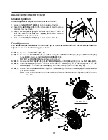
Hold the 

FAN(18)

 so that the 

FRONT SPROCKET

 is on your left side as shown.

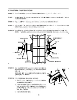
Loosen 

NUTS "A"

 and 

"B"

 until at least 

1/2"

 of 

FAN AXLE

 is showing between 

NUT "A"

 and

the 

FAN BUSHING.

Tighten 

NUT "C"

 completely until it bottoms out on the last 

FAN AXLE

 thread.

Tighten 

NUT "A"

 completely against 

FAN BUSHING,

 then back off 1/4 turn or until the 

FAN

AXLE

 has a very small amount of play side to side.

Hold 

NUT "A"

 and tighten 

NUT "B"

 completely against the 

SPEED PICKUP

 and 

NUT "A".

NOTE:

  The 

FAN

 should be able to spin freely on the 

FAN AXLE

 after completion of this step.

STEP  6:

STEP  7:

STEP  8:

STEP  9:

Reverse 

STEPS 1

 through 

4

 to reinstall the 

FAN(18),

FAN CAGES(28), CHAIN(17),

 and 

CHAIN GUARDS

(29, 30).
NOTE: DO NOT

 tighten 

NUTS(3/8"-26)(66)

 and 

NUTS

(M6x1)(65)

 until 

STEP 11.

The 

CHAIN


must

 be adjusted as follows:

STEP 12:

a.

b.

c.

Make sure the 

CHAIN(17)

 is on both the 

FRONT

and 

REAR SPROCKETS.

Tighten 

NUT(M6x1)(65)

 on 

EYE BOLTS(22)

 until all

slack is removed from 

CHAIN(17)

 and 

CENTER

 of

NUTS(3/8")(66)

 are the same distance from 

TAB

 on

both sides of 

BIKE.

Tighten 

NUTS(3/8")(66).

16

TAB

STEP 11:

FAN

NUT A

SPEED PICKUP

NUT B

WASHER

FAN BUSHING

FAN AXLE

NUT C

FRONT

SPROCKET

WAVY WASHER

FAN BUSHING

RESISTANCE HUB

WASHER

STEP 10:

Summary of Contents for 15-0960

Page 1: ...k Consult a physician before beginning any exercise program with this equipment If you feel faint or dizzy immediately discontinue use of this equipment Serious bodily injury can occur if this equipme...

Page 2: ...to commencing an exercise program If at any time during exercise you feel faint dizzy or experience pain stop and consult your physician Follow your physician s recommendations in developing your own...

Page 3: ...and on your way to achieving a happier and healthier lifestyle 3 Should you have any questions please call our Customer Service Department toll free number 1 800 375 7520 Monday Thursday 7 30 A M 5 0...

Page 4: ...d achieving a happier and healthier lifestyle Before reading further please review the drawing below and familiarize yourself with the parts that are labeled Read this manual carefully before using th...

Page 5: ...ess Place the washers the end of the bolts or screws on the circles to check for the correct diameter Use the small scale to check the length of the bolts and screws NOTICE The length of all bolts and...

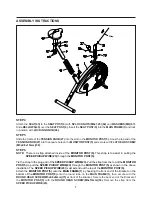
Page 6: ...fore beginning If you are missing a part please call our toll free number for assistance 1 800 375 7520 or e mail us at parts staminaproducts com STEP 1 Insert REAR SUPPORT 2 into the MAIN FRAME 1 and...

Page 7: ...ugh the MONITOR POST 5 as shown in the above illustration The SPEED PICKUP WIRE 23 must extend out the top of the MONITOR POST 5 Attach the MONITOR POST 5 onto the MAIN FRAME 1 by hooking the front en...

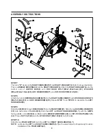
Page 8: ...1x12mm 59 and ARC WASHERS M6 70 Repeat STEP 7 and STEP 8 to assemble the LEFT HANDLEBAR 6 STEP 9 Slide the AXLE 36 through BUSHINGS 37 into the MAIN FRAME 1 Slide the two BUSHING WASHERS 38 onto both...

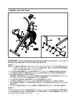
Page 9: ...until THIN NUTS 1 2 20 35 are tight against CRANK 10 Connect the LINKAGES 9 74 to the LINKAGE CONNECTORS 75 with the LOCKING PINS 76 a b c d e f g The RIGHT PEDAL 32 has R marked on the bottom side o...

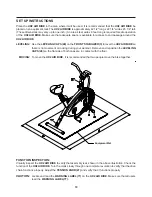
Page 10: ...1 2 long x 22 1 4 wide x 45 1 4 tall These dimensions may vary up to one inch An area 4 feet wide x 6 feet long is required for safe operation of the UX2 AIR BIKE Make sure that adequate space is ava...

Page 11: ...second up to 99 59 minutes Displays the current speed from zero to 999 9 miles per hour Displays the distance from zero to 99 99 miles Displays the calorie consumption from zero to 999 9 Kcal The cal...

Page 12: ...e seat If your leg is bent too much you will need to raise the seat Remove the LOCKING KNOB 46 Lower or raise the SEAT 43 to the desired height and secure with the LOCKING KNOB 46 The LOCKING KNOB 46...

Page 13: ...Workout Switch to the Stationary Handlebar position shown below As an alternative you may simply release the handlebars and place your hands on your hips or thighs as you pedal This concentrates the e...

Page 14: ...ll be replaced immediately or the UX2 AIR BIKE removed from service until repair is made Only Stamina Products supplied components shall be used to maintain repair the UX2 AIR BIKE Keep your UX2 AIR B...

Page 15: ...ter use To adjust the fan use the following procedures It is best to lift the front of the frame and remove the fan and fan cages thru the bottom of the bike Remove both PEDALS 31 32 Remove the SCREWS...

Page 16: ...be able to spin freely on the FAN AXLE after completion of this step STEP 6 STEP 7 STEP 8 STEP 9 Reverse STEPS 1 through 4 to reinstall the FAN 18 FAN CAGES 28 CHAIN 17 and CHAIN GUARDS 29 30 NOTE DO...

Page 17: ...maximum heart rate zone Start at the lower intensity and build up to higher intensity as you become more aerobically fit If you feel dizzy or lightheaded you should slow down or stop exercising Targe...

Page 18: ...our cool down should include the stretches listed above and should be completed after each strength training session Lower Body Stretch Place feet shoulder width apart and lean forward Keep this posit...

Page 19: ...transferable IF ANY PART OF THE PRODUCT IS NOT IN COMPLIANCE WITH THIS LIMITED WARRANTY OR ANY IMPLIED WARRANTY THE REMEDY OF REPAIR OR REPLACEMENT IS THE EXCLUSIVE REMEDY AVAILABLE TO YOU In the eve...

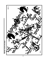
Page 20: ...PRODUCT PARTS DRAWING BACK FRONT 20...

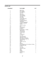
Page 21: ...tch 1 18 Fan 1 19 Resistance Hub 1 20 Fan Bushing 2 21 Fan Axle 1 22 Eye Bolt M6 x 1 x 55mm 2 23 Speed Pickup 1 24 Tension Spring 1 25 Tension Strap 1 26 Hook 1 27 Tension Knob 1 28 Fan Cage 2 29 Left...

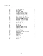
Page 22: ...ad M5 x 0 8 x 15mm 1 59 Bolt Round Head M6 x 1 x 12mm 4 60 Bolt Round Head M6 x 1 x 25mm 4 61 Bolt Hex Head M8 x 1 25 x 45mm 2 62 Nylock Nut M8 x 1 25 7 63 Nylock Nut M6 x 1 4 64 Acorn Nut M8 x 1 25 2...

Page 23: ...7520 in the U S from 7 30 A M to 5 00 P M Central Time Monday through Thursday and 8 00 A M to 3 00 P M on Friday or fill out the fax sheet ordering form below and fax it to 417 889 8064 Our Customer...

Reviews: