background image

ASSEMBLY INSTRUCTIONS

10

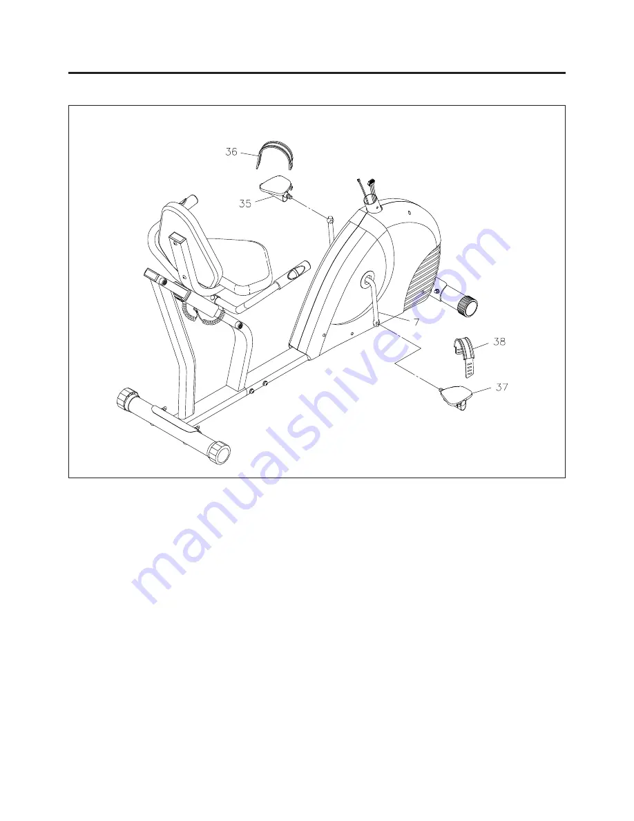
STEP 8

NOTE:

The 

RIGHT PEDAL(37)

 has 

R

 stamped on the end of the pedal shaft. The 

RIGHT PEDAL(37)

 has

right hand threads and is tightened by turning clockwise. The 

LEFT PEDAL(35)

 has 

L

 stamped on

the end of the pedal shaft. The 

LEFT PEDAL(35)

 has left hand threads and is tightened by turning

counterclockwise.

Thread the 

RIGHT PEDAL(37)

 into the right side of the 

CRANK(7)

 as shown. Tighten the pedal securely.

Select the 

RIGHT PEDAL STRAP(38)

 which has 

R

 marked on the bottom side of the strap. Snap the two

hole end to the inside edge of the 

RIGHT PEDAL(37).

 Snap the other end to the outside edge of the 

RIGHT

PEDAL(37)

 with the 

R

 mark on the bottom of the 

RIGHT PEDAL STRAP(38).

 Select adjustment holes

which allow your foot to be easily removed from the pedals.
Use the same procedure to attach the 

LEFT PEDAL(35)

 to the left side of the 

CRANK(7)

 and snap the

LEFT PEDAL STRAP(36)

 to the 

LEFT PEDAL(35).

Summary of Contents for 15-4550

Page 1: ...Serious bodily injury can also occur if all instructions are not followed Keep others and pets away from equipment when in use Always make sure all bolts and nuts are tightened prior to each use Follo...

Page 2: ...nd operate the Magnetic Fusion 4550 Bike on a solid level surface Do not position the Magnetic Fusion 4550 Bike on loose rugs or uneven surfaces Make sure that adequate space is available for access t...

Page 3: ...your way to achieving a happier and healthier lifestyle Should you have any questions please call our Customer Service Department toll free number 1 800 375 7520 Monday Thursday 7 30 A M 5 00 P M Cent...

Page 4: ...lease review the drawing below and familiarize yourself with the parts that are labeled Read this manual carefully before using the Magnetic Fusion 4550 Bike Although Stamina constructs its products w...

Page 5: ...is chart is provided to help identify the warning notice labels on the Magnetic Fusion 4550 Bike Please take a moment to familiarize yourself with all of the warning notice labels Label is larger than...

Page 6: ...1 2 3 1 2 4 1 2 5 1 2 6 1 2 0 10 20 30 40 50 60 70 80 90 100 110 120 130 140 150 6 8 10 12 3 16 5 16 1 2 3 8 1 4 length length After unpacking the unit open the hardware bag and make sure that you ha...

Page 7: ...nning If you are missing a part please call our toll free number for assistance 1 800 375 7520 or e mail us at customerservice staminaproducts com STEP 2 Attach the REAR STABILIZER 4 the one with the...

Page 8: ...ation B Slide the SEAT FRAME 5 onto the REAR FRAME 3 and lock in position with the ADJUSTMENT KNOB 50 Attach the STOPPERS 51 to the top end of the REAR FRAME 3 with HEX BOLT M8x1 25x80mm 60 and NUT M8...

Page 9: ...nds of the PULSE COIL WIRE 42 Connect both ends of the PULSE COIL WIRE 42 to the PULSE SENSOR WIRES 44 Push the plugs and excess wires back into the HANDRAIL 6 and secure with the GROMMET PLUGS 43 STE...

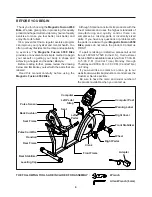
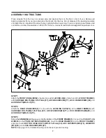
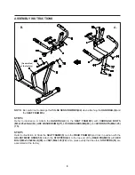
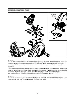
Page 10: ...nto the right side of the CRANK 7 as shown Tighten the pedal securely Select the RIGHT PEDAL STRAP 38 which has R marked on the bottom side of the strap Snap the two hole end to the inside edge of the...

Page 11: ...39 to the EXTENSION WIRE on the COMPUTER 27 Insert the COMPUTER POST 26 onto the FRONT FRAME 1 and secure with ROUND HEAD BOLTS M6x1x15mm 61 LOCK WASHERS M6 79 and ARC WASHERS M6 76 NOTE Be careful no...

Page 12: ...h the floor While you are adjusting the LEVELING CAPS 53 the STAND 54 must not be in contact with the floor Only after the Magnetic Fusion 4550 Bike has been stabilized with the LEVELING CAPS 53 will...

Page 13: ...ose to the pedals if you have more than a slight bend in your knees at the bottom of the pedal stroke The seat is too far from the pedals if you have to completely straighten your knees at the bottom...

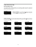
Page 14: ...DOWN BUTTONS Press to select programs P1 to P12 Press to decrease the values of the setting mode Press to decrease the level of the workload when running a program SET Press to confirm the selected pr...

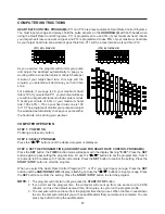
Page 15: ...lect the Heart Rate Control Programs P11 or P12 you must input your age This value affects only the Heart Rate Control Programs Press the SET button until the AGE TARGET H R display is flashing and us...

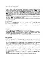
Page 16: ...Y P4 FAT BURN P5 RAMP P6 FITNESS TEST P7 RANDOM P8 PLATEAU P9 INTERVALS P10 MOUNTAIN MANUAL PROGRAM P1 is a manual program allowing the user to have full manual control of the workload Use the button...

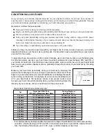
Page 17: ...rom the program time that you set When the timer counts down to zero the computer will alert you with an audible alarm that your workout is complete You can press any button to stop the audible alarm...

Page 18: ...n place and easy to read Call Stamina Products immediately at 1 800 375 7520 for a replacement WARNING LABEL 89 if it is missing or damaged It is the sole responsibility of the user owner to ensure th...

Page 19: ...mum heart rate zone Start at the lower intensity and build up to higher intensity as you become more aerobically fit If you feel dizzy or lightheaded you should slow down or stop exercising Target Hea...

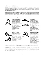
Page 20: ...cool down should include the stretches listed above and should be completed after each strength training session Lower Body Stretch Place feet shoulder width apart and lean forward Keep this position...

Page 21: ...LIVERY OF THE PRODUCT TO THE PURCHASER This limited warranty is not transferable IF ANY PART OF THE PRODUCT IS NOT IN COMPLIANCE WITH THIS LIMITED WARRANTY OR ANY IMPLIED WARRANTY THE REMEDY OF REPAIR...

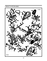
Page 22: ...PRODUCT PARTS DRAWING 22 FRONT BACK...

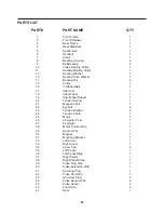
Page 23: ...er Wheel 1 19 Idler Wheel Spacer 1 20 Tension Spring 1 21 Magnetic Unit 1 22 Eyebolt 2 23 Tension Bracket 2 24 Tension Cable 1 25 Motor 1 26 Computer Post 1 27 Computer 1 28 Motor Control Wire 1 29 Se...

Page 24: ...ead M4 x 15mm 4 66 Screw Round Head M4 x 25mm 5 67 Screw Round Head M5 x 15mm 4 68 Screw Big Round Head M5 x 15mm 3 69 Thin Nut 3 8 26 x 5 32 thick 2 70 Nut 3 8 26 x 9 32 thick 2 71 Nut M6 x 1 2 72 Nu...

Page 25: ...25 NOTES...

Page 26: ...t be missing or a defective part found please call us from 7 30 A M to 5 00 P M Central Time Monday through Thursday and 8 00 A M to 3 00 P M on Friday or fill out the fax sheet ordering form below an...

Reviews: