background image

COMPUTER INSTRUCTIONS

12

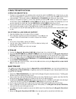
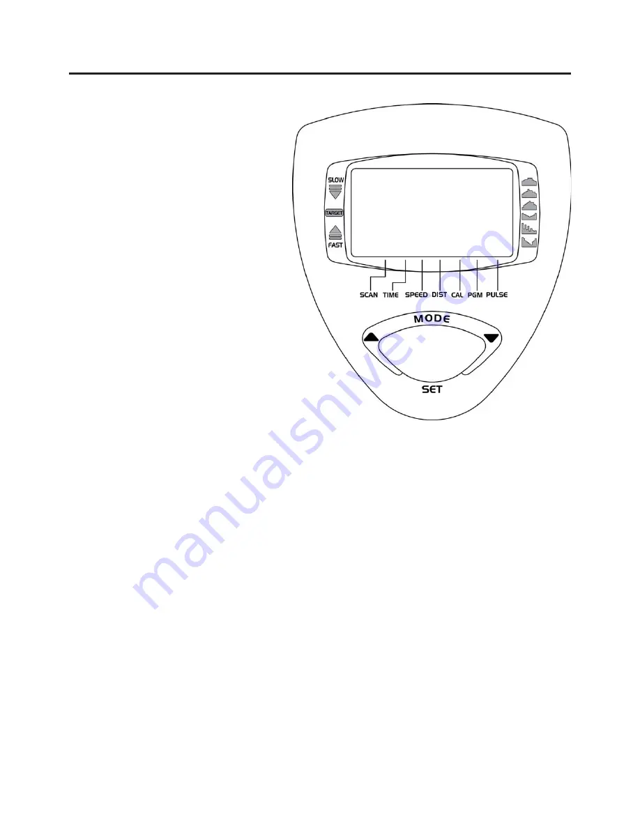
MAIN DISPLAY PANEL

LCD MONITOR:

1.

2.

This computer provides different programs
designed to help you meet your fitness
goals. Simply choose the program you like,
set the time for the workout, and begin
exercising. The computer display will show
the elapsed time, speed, distance, pulse,
and approximate calories burned.

LCD FEATURES


:

SCAN:

TIME:

SPEED:

DISTANCE:

CALORIES:

PROGRAM:

PULSE:

Displays the zone of current speed. The

 TARGET

 zone is preset by the program that you selected. Adjust

your pedaling speed to keep the current speed display within the 

TARGET

 zone. Refer to the instructions

on page 14 to read the 

TARGET

 zone correctly.

TARGET ZONE


:

The LCD displays TIME, SPEED,
DISTANCE, CALORIES, PROGRAM,
and PULSE.
Use the MODE, SET, UP, and DOWN
buttons to select a program and time.

Automatically scans each function of 

TIME, SPEED, DISTANCE, CALORIES, PROGRAM,

and 

PULSE 

in sequence with change every 5 seconds.

NOTE: 

 If you do not want to use the 

SCAN

 function, press the 

MODE 

button to select one of

the other functions.
Displays the time from one second up to 99:59 minutes.
Displays the current speed from zero to 999.9 miles per hour.
Displays the distance from zero to 99.99 miles.
Displays the calorie consumption from zero to 9999 Kcal.
The calorie readout is an estimate for an average user. It should be used only as a comparison
between workouts on this unit.
Displays programs for selection during setup from P0 to P6. Displays Target Speed during
exercise for programs P1 to P6.
Displays the pulse rate from 39 to 240 beats per minute.

NOTE:

  You must place both of your hands on the Pulse Sensors on the Handlebar to input the

pulse signal. If you do not place your hands correctly and 8 seconds passes without a pulse
input, the computer will turn off the pulse circuit. This is a power saving measure and you can
press 

MODE

 button to restart the pulse function.

OPERATIONAL INSTRUCTIONS

Summary of Contents for 15-4825B

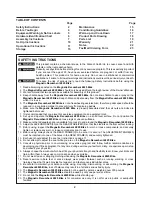
Page 1: ...s bodily injury can also occur if all instructions are not followed Keep others and pets away from equipment when in use Always make sure all bolts and nuts are securely tightened prior to each use Fo...

Page 2: ...ADJUSTMENT KNOB 45 must be inserted into one of the holes in the REAR FRAME 3 and securely tightened Each user should adjust the seat per instructions on page 11 Do not attempt to adjust the seat whi...

Page 3: ...e on your way to achieving a happier and healthier lifestyle Should you have any questions please call our Customer Service Department toll free number 1 800 375 7520 Monday Thursday 7 30 A M 5 00 P M...

Page 4: ...ng a happier and healthier lifestyle Before reading further please review the drawing below and familiarize yourself with the parts that are labeled Read this manual carefully before using the Magneti...

Page 5: ...is chart is provided to help identify the warning notice labels on the Magnetic Recumbent 4825 Bike Please take a moment to familiarize yourself with all of the warning notice labels Label is larger t...

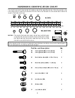
Page 6: ...on the circles to check for the correct diameter Use the small scale to check the length of the bolts and screws NOTICE The length of all bolts and screws except those with flat heads is measured fro...

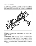
Page 7: ...ACORN NUTS M8x1 25 71 NOTE You can adjust the LEVELING CAPS 50 on the REAR STABILIZER 4 to keep the Recumbent Bike stable 7 STEP 1 Attach the FRONT STABILIZER 2 the short one with the WHEELS 49 to th...

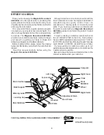
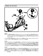
Page 8: ...WIRE 40 into the Socket of the PULSE EXTENSION WIRE 38 located on the REAR FRAME 3 STEP 4 Attach the SEAT 43 to the REAR FRAME 3 with ROUND HEAD BOLTS M6x1x20mm 61 STEP 5 Attach the BACK SUPPORT 5 to...

Page 9: ...to the Connection Wires of the COMPUTER 27 and push the excess wires back into the FRONT FRAME 1 Then insert the COMPUTER POST 26 into the FRONT FRAME 1 and secure with BUTTON HEAD BOLT M8x1 25x15mm 5...

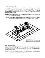
Page 10: ...e longest size to determine the size of the mat Adjust the LEVELING CAPS 50 on the REAR STABILIZER 4 so that the Recumbent Bike sits on the floor without rocking The Magnetic Recumbent 4825 Bike has a...

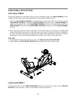
Page 11: ...our hips on the seat The seat is too close to the pedals if you have more than a slight bend in your knees at the bottom of the pedal stroke The seat is too far from the pedals if you have to complete...

Page 12: ...CALORIES PROGRAM and PULSE in sequence with change every 5 seconds NOTE If you do not want to use the SCAN function press the MODE button to select one of the other functions Displays the time from o...

Page 13: ...d is too fast or too slow NOTE PROGRAM 0 P0 This is a manual program You may set the TENSION KNOB 25 at any resistance level you choose You may change the TENSION KNOB 25 setting at any time during th...

Page 14: ...programs P0 P1 P2 P3 P4 P5 or P6 Press the UP or DOWN button to select a program Press the SET button when the desired program number appears You are now ready to set the program time STEP 3 SET THE...

Page 15: ...rmed Worn or damaged components shall be replaced immediately or the Magnetic Recumbent 4825 Bike removed from service until repair is made Only Stamina Products supplied components shall be used to m...

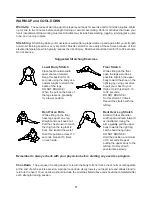
Page 16: ...aximum heart rate zone Start at the lower intensity and build up to higher intensity as you become more aerobically fit If you feel dizzy or lightheaded you should slow down or stop exercising Target...

Page 17: ...our cool down should include the stretches listed above and should be completed after each strength training session Lower Body Stretch Place feet shoulder width apart and lean forward Keep this posit...

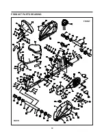
Page 18: ...PRODUCT PARTS DRAWING 18 FRONT BACK...

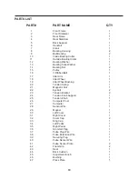
Page 19: ...Bushing 1 20 Tension Spring 1 21 Magnetic Unit 1 22 Eyebolt 2 23 Tension Bracket 2 24 Tension Knob Support 1 25 Tension Knob 1 26 Computer Post 1 27 Computer 1 28 Sensor Wire 1 29 Magnet 1 30 Left Co...

Page 20: ...x 1 x 20mm 8 62 Screw Round Head M5 x 0 8 x 15mm 4 63 Screw Round Head M5 x 0 8 x 20mm 1 64 Screw Round Head M5 x 15mm 6 65 Screw Small Round Head M5 x 25mm 4 66 Screw Round Head M4 x 8mm 2 67 Screw R...

Page 21: ...DELIVERY OF THE PRODUCT TO THE PURCHASER This limited warranty is not transferable IF ANY PART OF THE PRODUCT IS NOT IN COMPLIANCE WITH THIS LIMITED WARRANTY OR ANY IMPLIED WARRANTY THE REMEDY OF REP...

Page 22: ...22 NOTES...

Page 23: ...t be missing or a defective part found please call us from 7 30 A M to 5 00 P M Central Time Monday through Thursday and 8 00 A M to 3 00 P M on Friday or fill out the fax sheet ordering form below an...

Reviews: