background image

OPERATIONAL INSTRUCTIONS

12

SEAT HEIGHT ADJUSTMENT

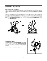
Proper seat height is important for efficient exercise. To determine proper seat height, sit on the BIKE and
center the ball of your foot on the pedal in the down position. Your leg should be slightly bent and relaxed as
shown.

If your leg is too straight or if your foot cannot touch the pedal when extended at the downstroke, you will
need to lower the seat. If your leg is bent too much, you will need to raise the seat. Remove the 

ADJUSTMENT

KNOB(43),

 lower or raise the 

SEAT(44)

 to the desired height, and secure with the 

ADJUSTMENT KNOB(43)

.

The 

ADJUSTMENT KNOB(43)

 should be screwed in tight to make the 

SEAT POST(6)

 fit securely

in the 

MAIN FRAME(1).

NOTE:

LOAD ADJUSTMENT

To increase the load, turn the 

TENSION KNOB(25)

 clockwise.

To decrease the load, turn the 

TENSION KNOB(25)

counterclockwise. There are eight levels for the load
adjustment.

NOTE:

  The load will increase as you pedal faster.

Summary of Contents for 15-5325

Page 1: ...rrectly Serious bodily injury can also occur if all instructions are not followed Keep others and pets away from equipment when in use Always make sure all bolts and nuts are tightened prior to each u...

Page 2: ...It is recommended that you place this exercise equipment on an equipment mat Set up and operate the Magnetic Upright 5325 Bike on a solid level surface Do not position the Magnetic Upright 5325 Bike o...

Page 3: ...on your way to achieving a happier and healthier lifestyle Should you have any questions please call our Customer Service Department toll free number 1 800 375 7520 Monday Thursday 7 30 A M 5 00 P M C...

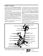
Page 4: ...g a happier and healthier lifestyle Before reading further please review the drawing below and familiarize yourself with the parts that are labeled Read this manual carefully before using the Magnetic...

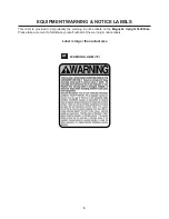
Page 5: ...his chart is provided to help identify the warning notice labels on the Magnetic Upright 5325 Bike Please take a moment to familiarize yourself with all of the warning notice labels Label is larger th...

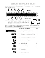
Page 6: ...eck for the correct diameter Use the small scale to check the length of the bolts and screws NOTICE The length of all bolts and screws except those with flat heads is measured from below the head to t...

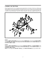
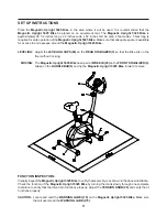
Page 7: ...M8 66 LOCK WASHERS M8 67 and ACORN NUTS M8x1 25 62 NOTE You can adjust the LEVELING CAPS 46 on the REAR STABILIZER 3 to keep the Bike stable Place all parts from the box in a cleared area and positio...

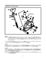
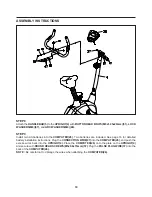
Page 8: ...sert the POST BUSHING 42 into the MAIN FRAME 1 Slide the POST SLEEVE 33 onto the MAIN FRAME 1 STEP 5 Attach the SEAT 44 to the SEAT POST 6 with NYLOCK NUTS M8x1 25 60 and WASHERS M8 67 Slide the BELLO...

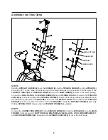
Page 9: ...the TENSION KNOB 25 firmly so that enough cable is available to insert the cable through the slot in the BRACKET Then insert the METAL FITTING on the cable of the TENSION KNOB 25 into the hole at the...

Page 10: ...teries are included See page 16 for detailed battery installation instructions Plug the CONNECTION WIRE 27 into the COMPUTER 26 and push the excess wires back into the UPRIGHT 4 Place the COMPUTER 26...

Page 11: ...LIZER 3 so that the Bike sits on the floor without rocking The Magnetic Upright 5325 Bike has a pair of WHEELS 45 on the FRONT STABILIZER 2 Grasp on the HANDLEBAR 5 and tip the Magnetic Upright 5325 B...

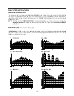
Page 12: ...downstroke you will need to lower the seat If your leg is bent too much you will need to raise the seat Remove the ADJUSTMENT KNOB 43 lower or raise the SEAT 44 to the desired height and secure with t...

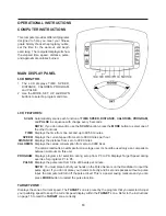
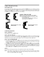
Page 13: ...CALORIES PROGRAM and PULSE in sequence with change every 5 seconds NOTE If you do not want to use the SCAN function press the MODE button to select one of the other functions Displays the time from o...

Page 14: ...d is too fast or too slow NOTE PROGRAM 0 P0 This is a manual program You may set the TENSION KNOB 25 at any resistance level you choose You may change the TENSION KNOB 25 setting at any time during th...

Page 15: ...programs P0 P1 P2 P3 P4 P5 or P6 Press the UP or DOWN button to select a program Press the SET button when the desired program number appears You are now ready to set the program time STEP 3 SET THE...

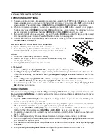
Page 16: ...ntenance is performed Worn or damaged components shall be replaced immediately or the Magnetic Upright 5325 Bike removed from service until repair is made Only Stamina Products supplied components sha...

Page 17: ...aximum heart rate zone Start at the lower intensity and build up to higher intensity as you become more aerobically fit If you feel dizzy or lightheaded you should slow down or stop exercising Target...

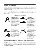
Page 18: ...our cool down should include the stretches listed above and should be completed after each strength training session Lower Body Stretch Place feet shoulder width apart and lean forward Keep this posit...

Page 19: ...ELIVERY OF THE PRODUCT TO THE PURCHASER This limited warranty is not transferable IF ANY PART OF THE PRODUCT IS NOT IN COMPLIANCE WITH THIS LIMITED WARRANTY OR ANY IMPLIED WARRANTY THE REMEDY OF REPAI...

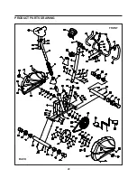
Page 20: ...PRODUCT PARTS DRAWING BACK FRONT 20...

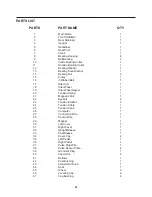
Page 21: ...er Wheel Spacer 1 20 Tension Spring 1 21 Magnetic Unit 1 22 Eyebolt 2 23 Tension Bracket 2 24 Tension Cable 1 25 Tension Knob 1 26 Computer 1 27 Connection Wire 1 28 Sensor Wire 1 29 Magnet 1 30 Left...

Page 22: ...Screw Round Head M5 x 25mm 4 57 Screw Round Head M5 x 0 8 x 15mm 4 58 Screw Round Head M5 x 0 8 x 50mm 1 59 Nut M6 x 1 2 60 Nylock Nut M8 x 1 25 3 61 Nylock Nut M10 x 1 5 x 7mm thick 2 62 Acorn Nut M8...

Page 23: ...t be missing or a defective part found please call us from 7 30 A M to 5 00 P M Central Time Monday through Thursday and 8 00 A M to 3 00 P M on Friday or fill out the fax sheet ordering form below an...

Reviews: