ASSEMBLY INSTRUCTIONS
11
STEP 9
NOTE:
The
RIGHT PEDAL(38)
has
R
stamped on the end of the pedal shaft. The
RIGHT PEDAL(38)
has
right hand threads and is tightened by turning clockwise. The
LEFT PEDAL(36)
has
L
stamped on
the end of the pedal shaft. The
LEFT PEDAL(36)
has left hand threads and is tightened by turning
counterclockwise.
Thread the
RIGHT PEDAL(38)
into the
RIGHT CRANK(33)
as shown. Tighten the pedal securely. Select
the
RIGHT PEDAL STRAP(39)
which has
R
marked on the bottom side of the strap. Snap the two hole end
to the inside edge of the
RIGHT PEDAL(38).
Snap the other end to the outside edge of the
RIGHT PEDAL(38)
with the
R
mark on the bottom of the
RIGHT PEDAL STRAP(39).
Select adjustment holes which allow your
foot to be easily removed from the pedals.
Use the same procedure to attach the
LEFT PEDAL(36)
to the
LEFT CRANK(32)
and snap the
LEFT
PEDAL STRAP(37)
to the
LEFT PEDAL(36).
STEP 10
Slide the
UPRIGHT SLEEVE(29)
over the
UPRIGHT(3).
Connect the
CONNECTION WIRE(25)
to the
CONTROL WIRE(24).
Insert the
UPRIGHT(3)
onto the
FRONT FRAME(1)
and secure with
FLAT HEAD
BOLTS(M8x1.25x15mm)(70).
Slide the
UPRIGHT SLEEVE(29)
down to cover the bolt heads.
Summary of Contents for 15-7100B
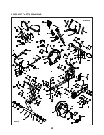
Page 22: ...PRODUCT PARTS DRAWING 22 FRONT BACK...
Page 25: ...25 NOTES...

