13
SET UP INSTRUCTIONS
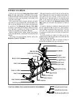
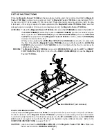
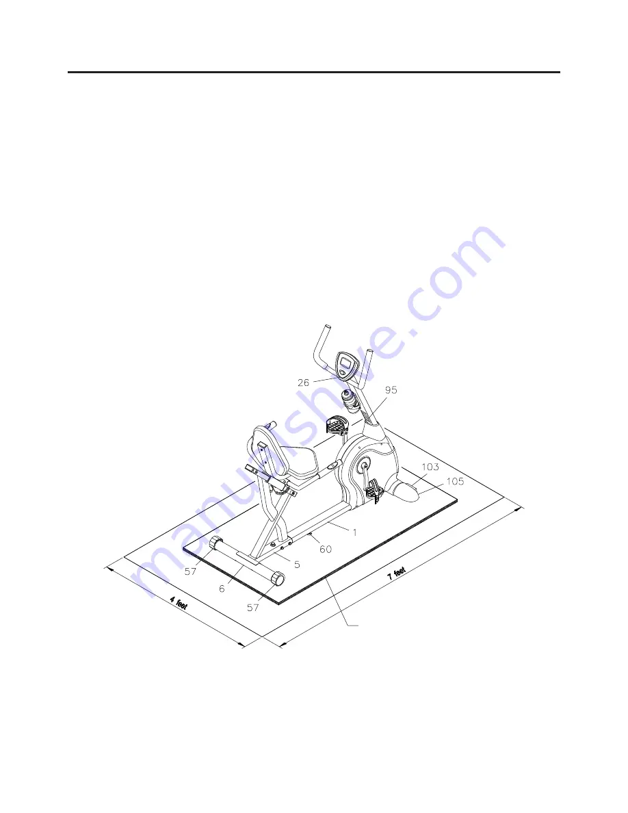
Place the
Magnetic Fusion 7100 Bike
in the area where it will be used. It is recommended that the
Magnetic
Fusion 7100 Bike
be placed on an equipment mat. The
Magnetic Fusion 7100 Bike
is approximately 53 1/4
inches long x 24 1/2 inches wide x 51 3/4 inches tall. (These dimensions may vary up to one inch.) An area
4 feet wide x 7 feet long is required for safe operation of the
Magnetic Fusion 7100 Bike.
Make sure that
adequate space is available for access to and passage around the
Magnetic Fusion 7100 Bike.
To level the
Magnetic Fusion 7100 Bike,
first screw the
STAND(60)
located in the middle of
the
FRONT FRAME(1)
all the way up into the
FRONT FRAME(1)
so that it is not touching the
floor.
Adjust the two
LEVELING CAPS(57)
on the
REAR STABILIZER(6).
When the
LEVELING
CAPS(57)
are adjusted and the
Magnetic Fusion 7100 Bike
is stable, rotate the
STAND(60)
to make it contact with the floor.
While you are adjusting the
LEVELING CAPS(57)
the
STAND(60)
must not be in contact with
the floor. Only after the
Magnetic Fusion 7100 Bike
has been stabilized with the
LEVELING
CAPS(57)
will you position the
STAND(60)
so it is in contact with the floor to provide extra
stability for the frame.
The
Magnetic Fusion 7100 Bike
has a pair of
WHEELS(103)
built into the
LEFT
and
RIGHT
FOOT CAPS(104, 105)
at the front. Lift up the
REAR STABILIZER(6)
to move the
Magnetic
Fusion 7100 Bike.
LEVELING:
MOVING:
FUNCTION INSPECTION:
Visually inspect the
Magnetic Fusion 7100 Bike
to verify that assembly is as shown in the above illustration.
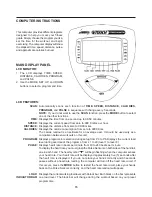
Check the function of the
Magnetic Fusion 7100 Bike
by turning the crank slowly through one complete
revolution to verify that the drive train functions properly. Use the
UP
and
DOWN
buttons on the
COMPUTER
(26)
to select a program and verify that the Magnetic System provides different tensions. Refer to the
COMPUTER INSTRUCTIONS
on pages 15 to 17.
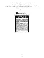
Locate and read the
WARNING LABEL(95)
on the
Magnetic Fusion 7100 Bike.
Make sure
that all users read the
WARNING LABEL(95).
CAUTION:
EQUIPMENT MAT
(not included)
Summary of Contents for 15-7100B
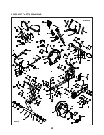
Page 22: ...PRODUCT PARTS DRAWING 22 FRONT BACK...
Page 25: ...25 NOTES...

