ASSEMBLY INSTRUCTIONS
9
A.
B.
(Assembled
at the factory)
STEP 5
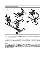
Refer to illustration A. Attach the
HANDRAIL(8)
to the
SEAT FRAME(7)
with
CARRIAGE BOLTS
(M8x1.25x45mm)(62), ARC WASHERS(M8)(86), LOCK WASHERS(M8)(88),
and
ACORN NUTS(M8x1.25)
(84).
STEP 6
Refer to illustration B. Slide the
SEAT FRAME(7)
onto the
REAR FRAME(5)
and lock in position with the
ADJUSTMENT KNOB(51).
Attach the
STOPPERS(52)
to the top end of the
REAR FRAME(5)
with
HEX
BOLT(M8x1.25x80mm)(68)
and
NUT(M8x1.25)(80).
Also, please verify that the other
STOPPERS(52)
are
assembled at the factory.
NOTE:
Be careful not to damage the
PULSE SENSOR WIRES(44)
when attaching the
HANDRAIL(8)
and
the
SEAT FRAME(7).
Summary of Contents for 15-7100B
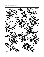
Page 22: ...PRODUCT PARTS DRAWING 22 FRONT BACK...
Page 25: ...25 NOTES...

