ASSEMBLY INSTRUCTIONS
12
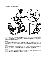
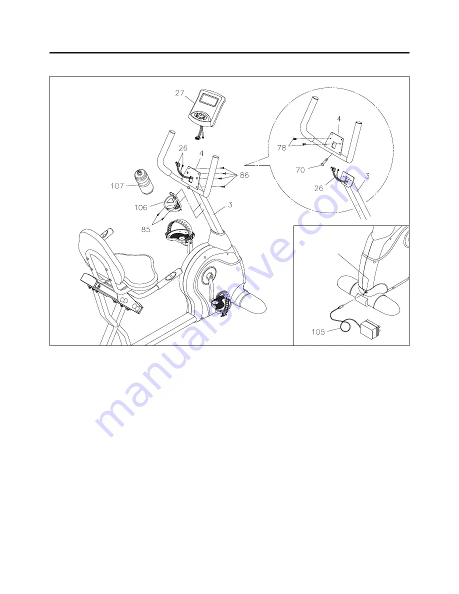
Socket of
Power Wire(28)
A.
B.
STEP 12
Refer to illustration A. Run the
CONNECTION WIRE(26)
through the hole in the plate on the
HANDLEBAR(4).
Attach the
HANDLEBAR(4)
to the
UPRIGHT(3)
with
BUTTON HEAD BOLT(M8x1.25x40mm)(70)
and
FLAT HEAD SCREWS(M6x1x12mm)(78).
STEP 13
Plug the
CONNECTION WIRE(26)
into the
EXTENSION WIRE
on the
COMPUTER(27).
Attach the
COMPUTER(27)
to the plate on the
HANDLEBAR(4)
with
ROUND HEAD SCREWS(M5x0.8x15mm)(86).
STEP 14
Attach the
MOUNTING BRACKET(106)
to the
UPRIGHT(3)
with
ROUND HEAD SCREWS
(M4x0.7x15mm)(85).
Place the
WATER BOTTLE(107)
in the
MOUNTING BRACKET(106).
STEP 15
Refer to illustration B. Plug the
ADAPTER(105)
into the
SOCKET
of the
POWER WIRE(28)
located on the
front of the bike.
Plug the
ADAPTER(105)
into an electrical outlet.
Summary of Contents for 15-7200
Page 22: ...PRODUCT PARTS DRAWING 22 FRONT BACK...
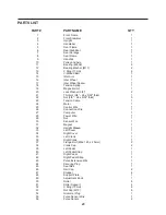
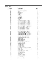
Page 26: ...26 NOTES...


