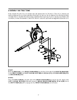
ASSEMBLY INSTRUCTIONS
8
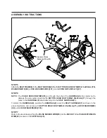
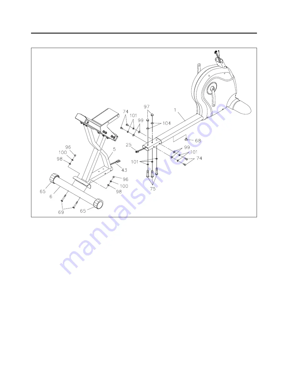
STEP 3
Attach the
REAR STABILIZER(6)
to the
REAR FRAME(5)
with
CARRIAGE BOLTS(M8x1.25x75mm)(69),
ARC WASHERS(M8)(98), LOCK WASHERS(M8)(100),
and
ACORN NUTS(M8x1.25)(96).
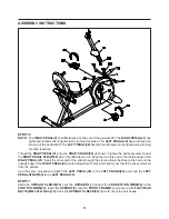
STEP 4
Screw the
STAND(68)
all the way up into the bottom of the
FRONT FRAME(1)
.
Connect the
PULSE
EXTENSION WIRE(43)
to the
CONTROL WIRE(25).
Insert the
REAR FRAME(5)
onto the
FRONT FRAME(1)
and secure with
BUTTON HEAD BOLTS(M10x1.5x20mm)(74), BUTTON HEAD BOLTS(M10x1.5x53mm)
(75), ARC WASHERS(M10)(99), WASHERS(M10)(104),
LOCK WASHERS(M10)(101),
and
ACORN
NUTS(M10x1.5)(97).
NOTE:
See page 13 for detailed leveling instructions to prevent rocking.
Summary of Contents for 15-7200
Page 22: ...PRODUCT PARTS DRAWING 22 FRONT BACK...
Page 26: ...26 NOTES...


