background image

ASSEMBLY INSTRUCTIONS

9

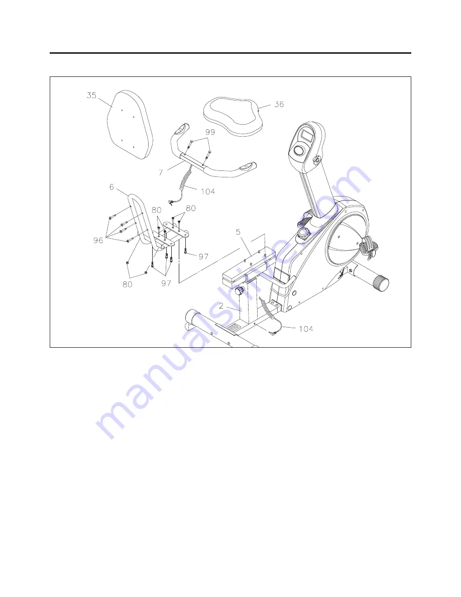
NOTE:

Be careful not to damage the 

PULSE SENSOR WIRES(104)

 while doing assembly Step 8 and       

Step 9.

STEP 7

Attach the 

SEAT FRAME(6)

 to the 

SEAT SUPPORT TUBE(5)

 with 

NYLOCK NUTS(M8x1.25)(80).

STEP 8

Attach  the 

HANDRAIL(7)

  to  the 

SEAT  FRAME(6)

  with 

CARRIAGE  BOLTS(M8x1.25x50mm)(99) 

and 

NYLOCK NUTS(M8x1.25)(80).

 Run the 

PULSE SENSOR WIRES(104)

 through the upright of the

 SEAT 

FRAME(6) 

and plug it into the socket on the 

REAR  FRAME(2).

STEP 9

Attach the 

SEAT(36)

 to the 

SEAT FRAME(6)

 with 

HEX BOLTS(M8x1.25x15mm)(97). 

Attach the 

BACK 

CUSHION(35)

 to the 

SEAT FRAME(6)

 with 

HEX BOLTS(M8x1.25x40mm)(96).

Summary of Contents for 15-9100C

Page 1: ...ury can occur if this equipment is not assembled and used correctly Serious bodily injury can also occur if all instructions are not followed Keep others and pets away from equipment when in use Alway...

Page 2: ...s on page 13 Do not attempt to adjust the seat while you are on the TOTAL BODY RECUMBENT BIKE Consult a physician prior to commencing an exercise program If at any time during exercise you feel faint...

Page 3: ...nd be on your way to achieving a happier and healthier lifestyle Should you have any questions please call our Customer Service Department toll free number 1 800 375 7520 Monday Thursday 7 30 A M 5 00...

Page 4: ...ting your body in shape and achieving a happier and healthier lifestyle Before reading further please review the drawing below and familiarize yourself with the parts that are labeled Read this manual...

Page 5: ...t is provided to help identify the warning caution and notice labels on the TOTAL BODY RECUMBENT BIKE Please take a moment to familiarize yourself with all of the warning caution and notice labels Lab...

Page 6: ...already attached to the part This chart is provided to help identify the hardware used in the assembly process Place the washers or the ends of the bolts or screws on the circles to check for the corr...

Page 7: ...EAR FRAME 2 with CARRIAGE BOLTS M8x1 25x85mm 79 and NYLOCK NUTS M8x1 25 80 Press the STAND CAPS 47 onto both sides of the REAR STABILIZER 9 Place all parts from the box in a cleared area and position...

Page 8: ...and is tightened by turning clockwise The LEFT PEDAL 25 has L stamped on the end of the pedal shaft The LEFT PEDAL 25 has left hand threads and is tightened by turning counterclockwise STEP 6 Insert...

Page 9: ...8x1 25 80 STEP 8 Attach the HANDRAIL 7 to the SEAT FRAME 6 with CARRIAGE BOLTS M8x1 25x50mm 99 and NYLOCK NUTS M8x1 25 80 Run the PULSE SENSOR WIRES 104 through the upright of the SEAT FRAME 6 and plu...

Page 10: ...STRUCTIONS 10 STEP 10 Attach the HANDLEBARS 51 to the MOUNTING BRACKETS 53 with the ADJUSTMENT KNOBS 52 and WASHERS M8 74 NOTE The HANDLEBARS 51 may be assembled in two configurations Refer to the ins...

Page 11: ...the TOTAL BODY RECUMBENT BIKE LEVELING FUNCTION INSPECTION Visually inspect the TOTAL BODY RECUMBENT BIKE to verify that assembly is as shown in the above illustration Check the function of the TOTAL...

Page 12: ...h an audible alarm when your pulse exceeds the set value Stop exercising until your pulse comes down AA Batteries 12 PRESET VALUES OPERATION Stop pedaling for four seconds Press the ENTER button to go...

Page 13: ...t and tighten the SEAT ADJUSTMENT LEVER 63 clockwise after adjusting the seat to a new position Refer to illustration 3 NOTE Please make sure to tighten the SEAT ADJUSTMENT LEVER 63 securely prior to...

Page 14: ...y be maintained when the TOTAL BODY RECUMBENT BIKE is regularly examined for damage and wear Special attention should be given to the following Adjust the TENSION KNOB 21 and verify that the Magnetic...

Page 15: ...to 90 higher intensity of your maximum heart rate zone Start at the lower intensity and build up to higher intensity as you become more aerobically fit If you feel dizzy or lightheaded you should slo...

Page 16: ...our cool down should include the stretches listed above and should be completed after each strength training session Lower Body Stretch Place feet shoulder width apart and lean forward Keep this posit...

Page 17: ...DELIVERY OF THE PRODUCT TO THE PURCHASER This limited warranty is not transferable IF ANY PART OF THE PRODUCT IS NOT IN COMPLIANCE WITH THIS LIMITED WARRANTY OR ANY IMPLIED WARRANTY THE REMEDY OF REPA...

Page 18: ...18 PRODUCT PARTS DRAWING FRONT BACK...

Page 19: ...rap 1 27 Right Pedal 1 28 Right Pedal Strap 1 29 Round Endcap 76mm 2 30 Moving Wheel 2 31 Pulley 250mm 1 32 Connection Wheel 1 33 Small Pulley 100mm 1 34 Magnet 1 35 Back Cushion 1 36 Seat 1 37 Rectan...

Page 20: ...10 2 87 Flange Nut M10 x 1 25 2 88 Bolt Hex Head M10 x 1 5 x 45mm 1 89 Idler Wheel Spacer 1 90 Nylock Nut M10 x 1 5 1 91 Wheel Shaft 1 92 Eye Bolt 1 93 Nylock Nut M6 x 1 1 94 Flange Bolt M8 x 1 25 x 2...

Page 21: ...NOTES 21...
Page 22: ...missing or a defective part found please call us from 7 30 A M to 5 00 P M Central Time Monday through Thursday and 8 00 A M to 3 00 P M on Friday or fill out the fax sheet ordering form below and fa...

Reviews: