background image

OPERATIONAL INSTRUCTIONS

The safety and integrity designed into the 

Stamina® BodyTrac Glider Rowing Machine 1052

 can only 

be maintained when the 

Stamina® BodyTrac Glider Rowing Machine 1052

 is regularly examined for 

damage and wear. Special attention should be given to the following:

1.  Pull on the 

HANDLEBARS(17, 18)

 and verify that the 

SHOCK(22)

 provides tension.

2.  Clean the roller tracks in the 

CENTER BEAM(1)

 with an absorbent cloth.

3. 

Verify  that  all  nuts  and  bolts  are  present  and  properly  tightened.  Replace  missing  nuts  and  bolts. 

Tighten loose nuts and bolts.

4. 

Verify that the 

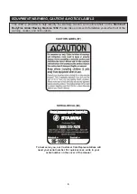
CAUTION LABEL(67)

 is in place and easy to read. Call Stamina Products immediately 

at 1-800-375-7520 for a replacement 

CAUTION LABEL(67)

 if it is missing or damaged.

5.  It is the sole responsibility of the user/owner to ensure that regular maintenance is performed.

6.  Worn or damaged components must be replaced immediately or the 

Stamina® BodyTrac Glider 

Rowing Machine 1052

 removed from service until repair is made.

7.  Only Stamina Products supplied components should be used to maintain/repair the 

Stamina® 

BodyTrac Glider Rowing Machine 1052.

8.  Keep your 

Stamina® BodyTrac Glider Rowing Machine 1052

 clean by wiping it off with an 

absorbent cloth after use.

MAINTENANCE

15

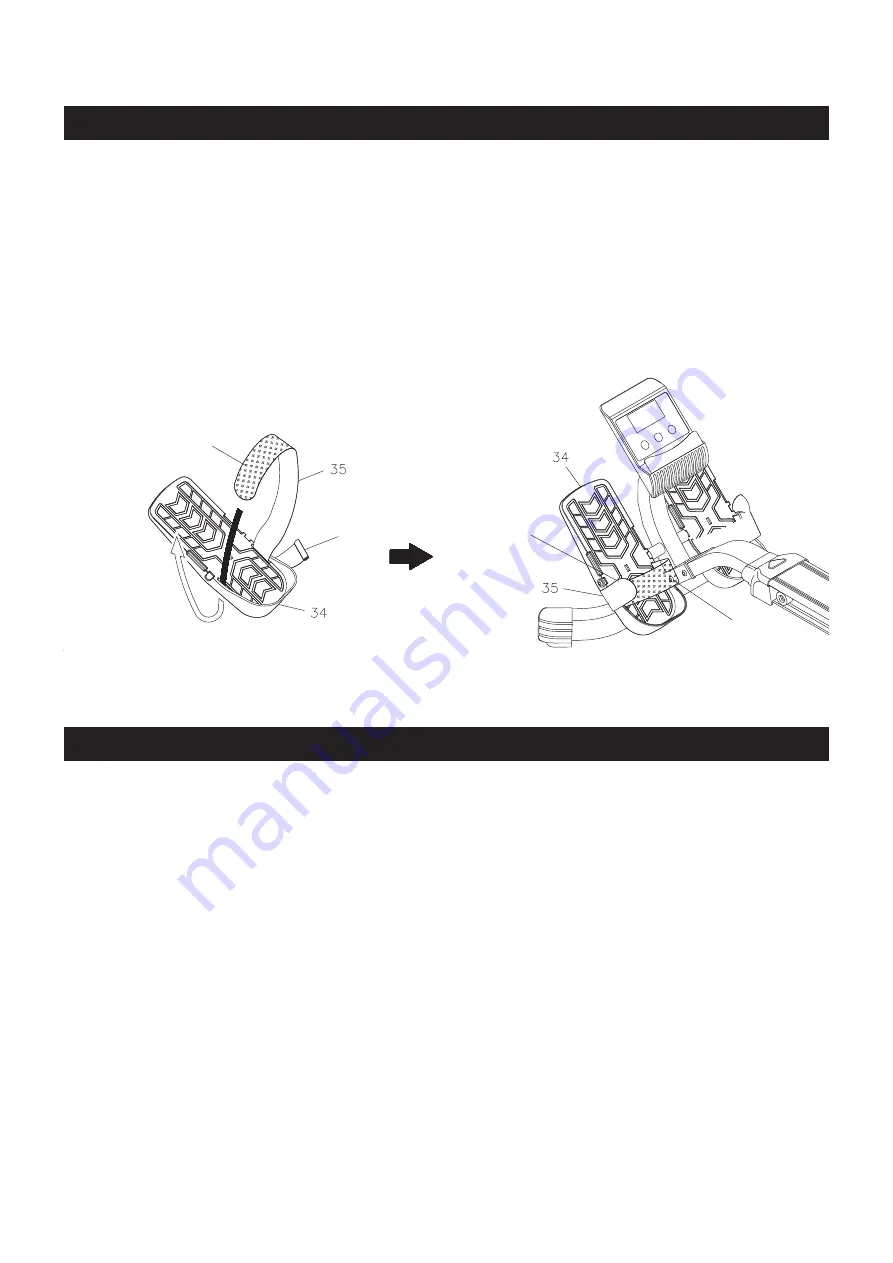
PEDAL STRAP ADJUSTMENT

Hook & Loop Pad

Hook & Loop Pad

1.

2.

End of Pedal Strap

Knot

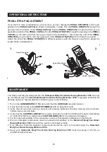
If you feel it is more comfortable for your workout, you can change the 

PEDAL STRAP(35) 

to the lower 

position in the 

PEDAL CAP(34)

 as shown in illustration 1 below. Run the 

PEDAL STRAP(35)

 through the 

opening from the bottom of the 

PEDAL CAP(34).

 Pull the 

PEDAL STRAP(35) 

to make the Knot secure 

against the bottom of the 

PEDAL CAP(34).

 Run the 

PEDAL STRAP(35)

 through the opening in the 

PEDAL 

CAP(34) 

on the other side from the top as shown in the illustration 1, then make the end of the 

PEDAL 

STRAP(35) 

go up to attach onto the upper part of the 

PEDAL STRAP(35)

 with the Hook & Loop Pad.

Attach the end of the 

PEDAL STRAP(35)

 to different positions with the Hook & Loop Pad to adjust the 

length. Refer to illustration 2.

Summary of Contents for 35-1052

Page 1: ...ous bodily injury can also occur if all instructions are not followed Keep others and pets away from equipment when in use Always make sure all bolts and nuts are securely tightened prior to each use...

Page 2: ......

Page 3: ...ring use To avoid burns do not touch the shock until it has time to cool 12 Consult a physician prior to commencing an exercise program and follow his her recommendations in developing your fitness pr...

Page 4: ...and to help us better serve you please go onlineand register your new product register staminaproducts com ONLINE customer care staminaproducts com www staminaproducts com TELEPHONE 1 800 375 7520 FA...

Page 5: ...se review the drawing below and familiarize yourself with the parts that are labeled Locate the serial decal on the product and write the serial number on the cover of the manual in the space provided...

Page 6: ...52 Please take a moment to familiarize yourself with all of the warning caution and notice labels EQUIPMENT WARNING CAUTION NOTICE LABELS 6 CAUTION LABEL 67 To best serve you our Customer Care Represe...

Page 7: ...head bolts and screws are measured from the top of the head to the end of the bolt or screw After unpacking the unit open the hardware bag and make sure that you have all the following fasteners Some...

Page 8: ...ustomer care staminaproducts com or call us toll free at 1 800 375 7520 in the U S Our Customer Care Staff is available to assist you from 7 30 A M to 5 00 P M Central Time Monday through Thursday and...

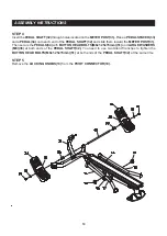
Page 9: ...METER POST 31 FRONT SUPPORT 26 and FRONT STABILIZER 28 together with BUTTON HEAD BOLTS M8x1 25x15mm 51 and WASHERS M8 59 Please do not tighten any of these bolts until all six bolts are attached NOTE...

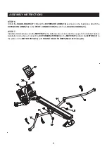
Page 10: ...AFT 32 and slide them toward the METER POST 31 Then secure the PEDALS 34 with BUTTON HEAD BOLTS M8x1 25x15mm 51 and LARGE WASHERS M8 36 at both ends of the PEDAL SHAFT 32 You need to use two Allen Wre...

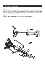
Page 11: ...ARMS 14 to the PIVOT CONNECTOR 10 with the LOCKING KNOBS 13 STEP 7 Install twoAAAbatteries into the METER 37 the batteries are not included See page 14 for detailed battery installation instructions C...

Page 12: ...3 to the back end of the CENTER BEAM 1 with BUTTON HEAD BOLTS M8x1 25x25mm 53 WASHERS M8 59 and NYLOCK NUTS M8x1 25 62 Also please verify that the other SEAT STOPPERS 3 at the front end of the CENTER...

Page 13: ...o 99 59 minutes Counts down from preset value Displays the total number of rows you have taken from zero to 9999 rows Counts down from preset value Displays the calorie burned from zero to 999 9 Kcal...

Page 14: ...ay preset values for several functions The preset function values will start to count down When you complete one of the preset functions the value of this completed function will start to count up whi...

Page 15: ...dyTrac Glider Rowing Machine 1052 removed from service until repair is made 7 Only Stamina Products supplied components should be used to maintain repair the Stamina BodyTrac Glider Rowing Machine 105...

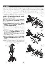
Page 16: ...ider Rowing Machine 1052 as illustrated for easy storage B D C Folding the Stamina BodyTrac Glider Rowing Machine 1052 A Slide the SEAT 42 to the front end of the CENTER BEAM 1 Remove the LOCKING KNOB...

Page 17: ...of your maximum heart rate zone Start at the lower intensity and build up to higher intensity as you become more aerobically fit If you feel dizzy or lightheaded you should slow down or stop exercisin...

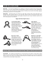
Page 18: ...cool down should include the stretches listed above and should be completed after each strength training session Lower Body Stretch Place feet shoulder width apart and lean forward Keep this position...

Page 19: ...RANTY INCLUDING MERCHANTABILITY AND FITNESS FOR A PARTICULAR PURPOSE MAY BE COMMENCED MORE THAN ONE 1 YEAR AFTER DELIVERY OF THE PRODUCT TO THE PURCHASER These warranties are not transferable IF ANY P...

Page 20: ...PRODUCT PARTS DRAWING 20 FRONT BACK...

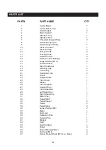
Page 21: ...her M12 2 17 Left Handlebar 1 18 Right Handlebar 1 19 Securing Cap 2 20 Foam Grip 2 21 Handlebar Cap 2 22 Shock 1 23 Support Plate 1 24 Front Cover 1 25 Sleeve 1 26 Front Support 1 27 Support Ring 1 2...

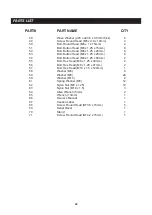
Page 22: ...x 25mm 6 54 Bolt Button Head M8 x 1 25 x 50mm 2 55 Bolt Hex Head M8 x 1 25 x 30mm 4 56 Bolt Hex Head M8 x 1 25 x 41mm 2 57 Bolt Hex Head M10 x 1 5 x 120mm 1 58 Washer M6 4 59 Washer M8 24 60 Washer M1...

Page 23: ...nvenience Stamina s customer care representatives can be reached by email at customer care staminaproducts com or by phone at 1 800 375 7520 in the U S Our customer care representatives are available...

Reviews: