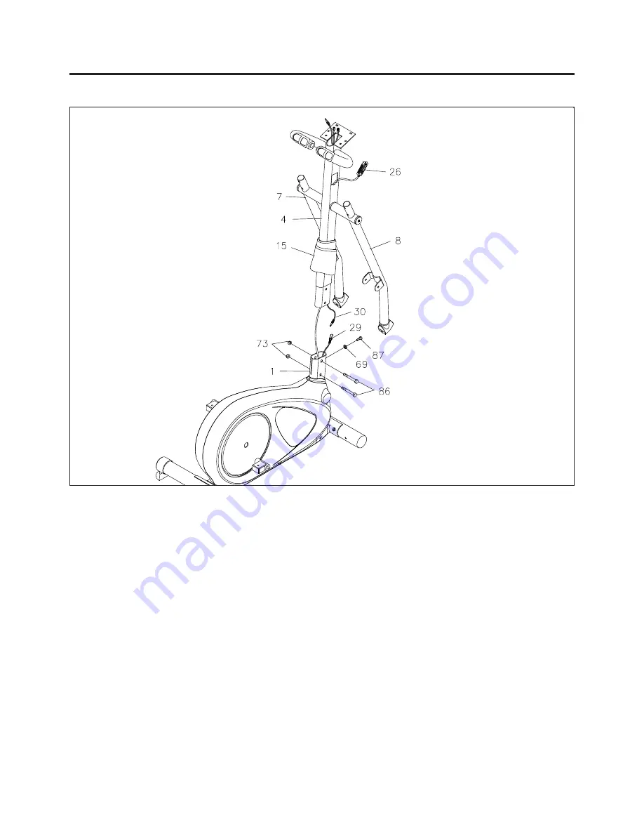
ASSEMBLY INSTRUCTIONS
7
STEP 3
Slide the
UPRIGHT SLEEVE(15)
onto the
UPRIGHT(4).
Slide the
TENSION CABLE(26)
into the
bottom end of the
UPRIGHT(4).
Pull the end of the
TENSION CABLE(26)
through the square hole in
the
UPRIGHT(4). CAUTION:
Be careful not to damage the
CONNECTION WIRE(30).
Connect the
CONNECTION WIRE(30)
to the
SENSOR WIRE(29).
Insert the
UPRIGHT(4)
into the
MAIN
FRAME(1)
and secure with
HEX BOLTS(M8 x 20mm)(87), LOCK WASHER(M8)(69), HEX
BOLTS(M8 x 50mm)(86),
and
NYLOCK NUTS(M8)(73).
Slide the
UPRIGHT SLEEVE(15)
down to
cover the bolts on the
UPRIGHT(4).
Summary of Contents for 55-2010
Page 18: ...18 PRODUCT PARTS DRAWING FRONT BACK...
Page 22: ...22 NOTES...


