10
OPERATIONAL INSTRUCTIONS
Over time your
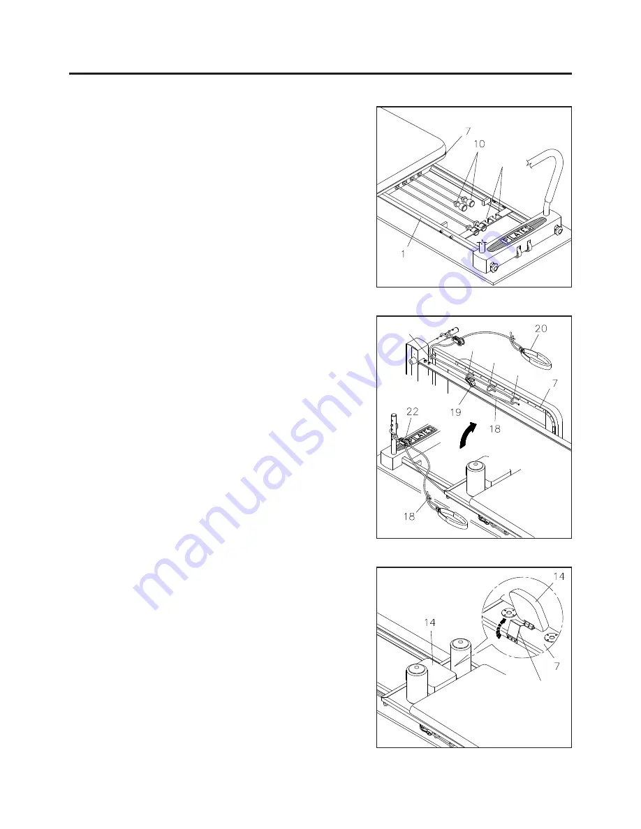
TENSION CORDS(10)
will relax. To
increase resistance in the
TENSION CORDS(10),
stretch and re-tie the tension cords in a more taut
position.
B
C
Support
Bracket
LOAD ADJUSTMENT
The resistance of the
CARRIAGE(7)
can be adjusted by
securing the
TENSION CORDS(10)
in the slots on the
FRONT
FRAME(1).
You can achieve various levels of resistance by
securing different numbers of the
TENSION CORDS(10)
in
the slots.
NOTE:
Slots
WARNING:
Always ensure that the
HEADREST(14)
and
support bracket
are correctly positioned before use.
D
ROPE LENGTH ADJUSTMENT
The
ROPES(18)
feed through the
PULLEY SETS(22)
then
thread through the loops on the underside of both outer edges
of the
CARRIAGE(7).
PLASTIC SNAP HOOKS(19)
on the
end of each rope are used to adjust the
ROPE(18)
length. If
more length is needed, attach the
PLASTIC SNAP HOOKS
(19)
to loop D. To shorten, bring the
ROPES(18)
around the
last loop D and secure to loops A, B, or C with the
PLASTIC
SNAP HOOKS(19).
Wrap
ROPES(18)
through the loops and
attach where needed to shorten
ROPES(18)
even more.
HEADREST ADJUSTMENT
The
HEADREST(14)
on the
CARRIAGE(7)
can be positioned
flat or at an incline by simply pivoting the support bracket
underneath the
HEADREST(14).
A
Summary of Contents for 55-4690
Page 14: ...PRODUCT PARTS DRAWING 14 FRONT BACK ...
Page 18: ...NOTES 18 ...


