background image

6

length

length

mm.

in.

INCHES

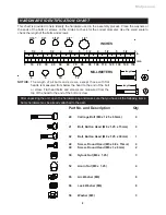
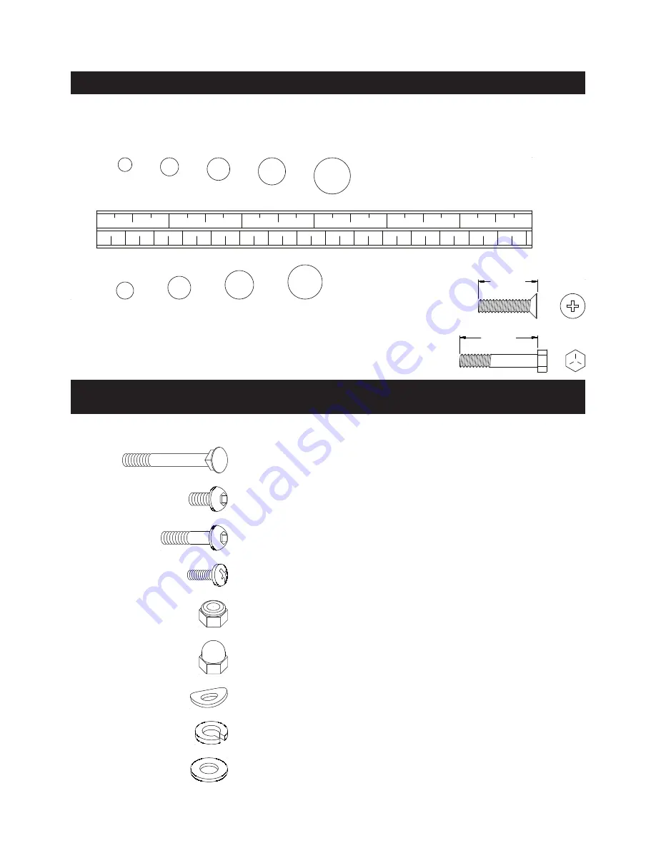
This chart is provided to help identify the hardware used in the assembly process. Place the washers or 

the ends of the bolts or screws on the circles to check for the correct diameter. Use the small scale to 

check the length of the bolts and screws.

NOTICE: 

The  length  of  all  bolts  and  screws,  except  those  with  flat 

heads, is measured from below the head to the end of the bolt 

or screw. Flat head bolts and screws are measured from the 

top of the head to the end of the bolt or screw.

After unpacking the unit, open the hardware bag and make sure that you have all the following items. 

Some hardware may be already attached to the part.

MILLIMETERS


10  20  30  40  50  60  70  80  90  100  110  120  130  140  150


1/2 

1/2 

1/2 

1/2 

1/2 

1/2 

6


10 

12


3/16" 

1/4" 

5/16" 

3/8" 

1/2"

HARDWARE IDENTIFICATION CHART

Part No. and Description   


Qty

40 

Carriage Bolt (M8 x 1.25 x 65mm)   

    4

41 

Bolt, Button Head (M8 x 1.25 x 15mm) 

    4

56 

Lock Washer (M8)   


    8

52 

Acorn Nut (M8 x 1.25) 


    4

58 

Washer (M8)   


    3

55 

Arc Washer (M8) 


    8

48 

Screw, Round Head (M5 x 0.8 x 15mm)      4

49 

Screw, Round Head (M6 x 1 x 8mm) 

    2

42 

Bolt, Button Head (M8 x 1.25 x 30mm) 

    1

50 

Nylock Nut (M8 x 1.25) 


    3

Meijer.com

Summary of Contents for A150-100

Page 1: ...Stamina Products Inc 2011 06 Exercise can present a health risk Consult a physician before beginning any exercise program with this equipment If you feel faint or dizzy immediately discontinue use of...

Page 2: ...t be inserted into one of the holes in the SEAT POST 6 and securely tightened 13 Each user should adjust the seat per instructions on page 12 14 Do not attempt to adjust the seat while you are on the...

Page 3: ...tomer Service Department toll free number 1 800 375 7520 Monday Thursday 7 30 A M 5 00 P M Central Time Friday 8 00 A M 3 00 P M Central Time TELEPHONE CUSTOMER SERVICE Tel 1 800 375 7520 FAX CUSTOMER...

Page 4: ...the finest materials and uses the highest standards of manufacturing and quality control there can sometimes be missing parts or incorrectly sized parts If you have any questions or problems with the...

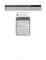
Page 5: ...ded to help identify the warning caution and notice labels on the AVARI Upright Bike Please take a moment to familiarize yourself with all of the warning caution and notice labels EQUIPMENT WARNING CA...

Page 6: ...to the end of the bolt or screw After unpacking the unit open the hardware bag and make sure that you have all the following items Some hardware may be already attached to the part MILLIMETERS 0 10 20...

Page 7: ...roducts com or call us toll free at 1 800 375 7520 in the U S Our Customer Service Staff is available to assist you from 7 30 A M to 5 00 P M Central Time Monday through Thursday and 8 00 A M to 3 00...

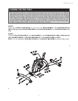
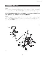
Page 8: ...ed by turning counterclockwise Thread the RIGHT PEDAL 32 to the right side of the CRANK 7 as shown Tighten the pedal securely Do the same to attach the LEFT PEDAL 31 to the left side of the CRANK 7 ST...

Page 9: ...KNOB 23 to the SPRING HOOK on the end of the TENSION CABLE 22 c Pull on the Cable of the TENSION KNOB 23 firmly so that enough cable is available to allow the METAL FITTING go through the slot in the...

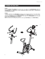
Page 10: ...Install two AA batteries into the METER 24 the batteries are not included See page 13 for detailed battery installation instructions Plug the CONNECTION WIRE 25 into the METER 24 and push the excess w...

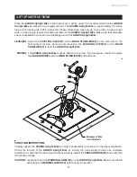
Page 11: ...eposition the LEVELING CAPS 38 on the REAR STABILIZER 3 to level the AVARI Upright Bike MOVING The AVARI Upright Bike must be lifted to be moved Two people are required to grasp the HANDLEBAR 5 and th...

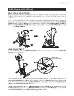
Page 12: ...in tight to make the SEAT POST 6 fit securely in the MAIN FRAME 1 LOAD ADJUSTMENT To increase the load turn the TENSION KNOB 23 clockwise To decrease the load turn the TENSION KNOB 23 counterclockwise...

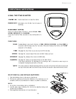
Page 13: ...ISTANCE and CALORIES in sequence with change every four seconds Press and release the button until SCAN appears on the display Displays the time from one second up to 99 59 minutes Displays the curren...

Page 14: ...se a wrench to verify that the pedals are tightened securely If tightening is required remember that the left pedal has left hand threads and is tightened by turning counterclockwise 3 Verify that all...

Page 15: ...r maximum heart rate zone Start at the lower intensity and build up to higher intensity as you become more aerobically fit If you feel dizzy or lightheaded you should slow down or stop exercising To d...

Page 16: ...down should include the stretches listed above and should be completed after each strength training session Lower Body Stretch Place feet shoulder width apart and lean forward Keep this position for 3...

Page 17: ...OF THE PRODUCT TO THE PURCHASER This limited warranty is not transferable IF ANY PART OF THE PRODUCT IS NOT IN COMPLIANCE WITH THIS LIMITED WARRANTY OR ANY IMPLIED WARRANTY THE REMEDY OF REPAIR OR REP...

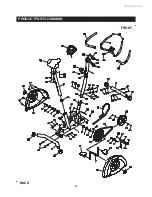
Page 18: ...PRODUCT PARTS DRAWING 18 FRONT BACK Meijer com...

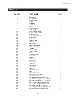
Page 19: ...eel 1 22 Tension Cable 1 23 Tension Knob 1 24 Meter 1 25 Connection Wire 1 26 Sensor Wire 1 27 Magnet 1 28 Left Cover 1 29 Right Cover 1 30 Cover Cap 2 31 Left Pedal 1 32 Right Pedal 1 33 Foam Grip 2...

Page 20: ...k Nut M10 x 1 5 x 7mm thick 1 52 Acorn Nut M8 x 1 25 4 53 Thin Nut 3 8 26 x 5 32 thick 2 54 Nut 3 8 26 x 9 32 thick 2 55 Arc Washer M8 8 56 Lock Washer M8 8 57 Large Washer 16 5 x 32 x 0 5mm thick 1 5...

Page 21: ...NOTES 21 Meijer com...

Page 22: ...SERVICE For your convenience Stamina s customer service representatives can be reached by email at customerservice staminaproducts com or by phone at 1 800 375 7520 in the U S Our customer service rep...

Reviews: