ASSEMBLY INSTRUCTIONS
8
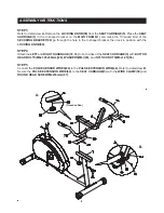
STEP 3
Refer to detail view
A.
Remove the
LOCKING KNOB(59)
from the
SEAT CARRIAGE(5).
Place the
SEAT
CARRIAGE(5)
in the U-shaped bracket on the
MAIN FRAME(1)
and make the Threaded Rod of the
SECURING BRACKET(69)
go through the hole in the U-shaped bracket, then lock in position with the
LOCKING KNOB(59).
STEP 4
Attach the
LEFT
and
RIGHT HANDRAILS(72, 16)
to both sides of the
SEAT CARRIAGE(5)
with
BUTTON
HEAD BOLTS(M8x1.25x50mm)(28), WASHERS(M8)(49),
and
NYLOCK NUTS(M8x1.25)(50).
STEP 5
Connect the
PULSE SENSOR WIRES(64)
to the
PULSE EXTENSION WIRE(44).
Refer to detail view
B.
Secure the
PULSE EXTENSION WIRE(44)
to the
SEAT CARRIAGE(5)
with the
WIRE CLAMP(39)
and
ROUND HEAD SCREW(M4x16mm)(67).
A.
B.
(Threaded Rod)
Summary of Contents for A150-210
Page 18: ...PRODUCT PARTS DRAWING 18 FRONT BACK ...
Page 22: ...NOTES 22 ...


