background image

USING THE MONITOR

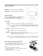
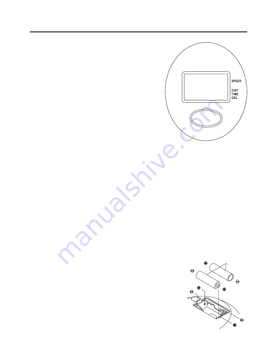
AA Batteries

Open the Battery Door on the back of the monitor.
The monitor operates with two AA batteries, two batteries included.
Refer to the illustration to install or replace the batteries.

1.
2.

Do not mix a new battery with an old battery.
Use the same type of battery.  Do not mix an alkaline battery with
another type of battery.
Rechargeable batteries are not recommended.

1.
2.

3.

NOTE:

CALORIES:

13

HOW TO INSTALL AND REPLACE BATTERIES:

TIME:

Displays the current speed on upper display, from zero to 999.9 Mile/Hr.

Lower display automatically scans 

DISTANCE, TIME, 

and 

CALORIES

 in sequence with

a change every four seconds.  Press and release the 

MODE

 button until 

"SCAN"

 appears

on the display.

Displays the distance, from zero to 999.9 miles.

Displays the time, from 1 sec. up to 99:59 minutes.

Displays the calorie consumption, from zero to 999.9 cal.
The calorie readout is an estimate for an average user.  It should be used only as a
comparison between workouts on this unit.

SPEED:

FUNCTIONS:

SCAN:

DISTANCE:

Pedal movement or push the 

BUTTON.

Automatic shut off after 2 minutes of inactivity.

POWER OFF :

POWER  ON :

FUNCTION BUTTON:

Press to select lower display functions.  Lower display functions
include 

SCAN, DISTANCE, TIME,

 and 

CALORIES.

Press and hold for three seconds to reset all functions to zero.

The monitor will shut off automatically after 2 minutes of inactivity.  All function values will
be kept.  Push the 

BUTTON

 and hold it down for three seconds to reset all functions to

zero.

NOTE:

Summary of Contents for Dual-Action 955

Page 1: ...ep others and pets away from equipment when in use Always make sure all bolts and nuts are tightened prior to each use Follow all safety instructions in this manual When calling for parts or service please specify the following number 15 0955 STAMINAPRODUCTS MADE IN CHINA Product May Vary Slightly From Pictured CAUTION Weight on this product should not exceed 250 lbs 2005 09 2040 N Alliance Spring...

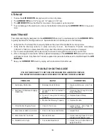
Page 2: ...ts prior to using the AIR BIKE 955 Consult a physician prior to commencing an exercise program If at any time during exercise you feel faint dizzy or experience pain stop and consult your physician Follow your physician s recommendations in developing your own personal fitness program Always choose the workout which best fits your physical strength and flexibility level Know your limits and train ...

Page 3: ...ception of those few parts left unassembled for shipping purposes Simply follow the few assembly instructions set forth in this manual Within a few minutes you will be getting your body into shape and on your way to achieving a happier and healthier lifestyle Should you have any questions please call our Customer Service Department toll free number 1 800 375 7520 Monday Friday 8 00 A M 5 00 P M Ce...

Page 4: ... with the finest materials and uses the highest standards of manufacturing occasionally a part that does not fit is the incorrect size or is otherwise inappropriate is found Even with the highest inspection and quality controls in place these things will happen occasionally Please do not return the product For your convenience Stamina has a Customer Service Department with a toll free number If a ...

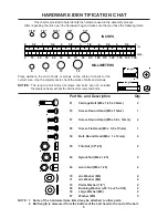
Page 5: ...asured from the bottom of the bolt head to the end of the bolt NOTE HARDWARE IDENTIFICATION CHAT Place washers the end of bolts or screws on the circles to check for the correct size Use the small scale to check the sizes of bolts and screws This chart is provided to help identify the hardware used in the assembly process After unpacking the unit open the hardware bag and make sure that you have t...

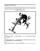
Page 6: ...lly before beginning If you are missing a part please call our toll free number for assistance 1 800 375 7520 or e mail us at parts staminaproducts com STEP 1 Insert REAR SUPPORT 2 into the MAIN FRAME 1 and fasten with ROUND HEAD SCREWS M5 x 12mm 57 STEP 2 Attach FRONT STABILIZER 3 onto the MAIN FRAME 1 with CARRIAGE BOLTS M8 x 38mm 51 ARC WASHERS M8 71 and ACORN NUTS M8 64 STEP 3 Turn the LEVELIN...

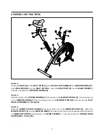
Page 7: ...SION KNOB 27 into the slot on the MONITOR POST 5 Hook the top end of the TENSION KNOB 27 into the square hole on the MONITOR POST 5 and secure with FLAT HEAD SCREW M5 x 15mm 58 STEP 6 Slide the SPEED PICKUP WIRE 23 into the bottom end of the MONITOR POST 5 Attach the MONITOR POST 5 onto the MAIN FRAME 1 by hooking the front end of the Bracket at the bottom of the MONITOR POST 5 into the slot on th...

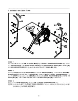
Page 8: ...S 37 into the MAIN FRAME 1 Slide the two BUSHING WASHERS 38 onto both sides of the AXLE 36 Slide the LEFT and RIGHT HANDLEBARS 6 7 with the GRIPS facing outside onto AXLE 36 and fasten with LARGE WASHERS M8 39 and NYLOCK NUTS M8 62 Place a NUT CAP 40 onto the NYLOCK NUT M8 62 on both sides STEP 9 Slide the two FOAM GRIPS 41 onto the LEFT and RIGHT HANDLEBARS 6 7 NOTE R Lubricate the LEFT and RIGHT...

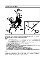
Page 9: ...NUTS 1 2 35 until THINNUTS 1 2 35 are tight against CRANK 10 a b c d e f The RIGHT PEDAL 32 has R marked on the bottom side of the pedal The LEFT PEDAL 31 has L marked on the bottom side of the pedal Both PEDALS 31 32 have RIGHTHAND THREADS Tighten both PEDALS 31 32 by turning clockwise STEP 10 NOTE IMPORTANT STUDY THE ABOVE ILLUSTRATION AND READ ALL OF STEP 10 a through f BEFORE ATTACHING PEDALS ...

Page 10: ...IR BIKE 955 is approximately 42 1 2 long x 22 1 4 wide x 45 1 4 tall These dimensions may vary up to one inch An area 4 feet wide x 6 feet long is required for safe operation of the AIR BIKE 955 Make sure that adequate space is available for access to and passage around the AIR BIKE 955 Adjust the LEVELING CAPS 48 on the FRONT STABILIZER 3 so that the bike sets on the floor without rocking Remove ...

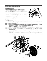
Page 11: ...he seat If your leg is bent too much you will need to raise the seat Remove the LOCKING KNOB 46 Lower or raise the SEAT 43 to the desired height and secure with the LOCKING KNOB 46 The LOCKING KNOB 46 must be inserted into one of the holes in the SEAT POST 4 The LOCKING KNOB 46 should be screwed in tight to make the SEAT POST 4 fit securely in the MAIN FRAME 1 CAUTION NOTE LOAD ADJUSTMENT To incre...

Page 12: ... while simultaneously pedaling Alternate the effort to your arms or legs to intensify or reduce the work of the upper or lower body The handlebars may be gripped from underneath palm up to change the muscle groups used in the arms Lower Body Workout Simply release the handlebars and place your hands on your hips or thighs as you pedal This concentrates the exercise on the lower body Upper Body Wor...

Page 13: ...d release the MODE button until SCAN appears on the display Displays the distance from zero to 999 9 miles Displays the time from 1 sec up to 99 59 minutes Displays the calorie consumption from zero to 999 9 cal The calorie readout is an estimate for an average user It should be used only as a comparison between workouts on this unit SPEED FUNCTIONS SCAN DISTANCE Pedal movement or push the BUTTON ...

Page 14: ...all be replaced immediately or the AIR BIKE 955 removed from service until repair is made Only Stamina Products supplied components shall be used to maintain repair the AIR BIKE 955 Keep your AIR BIKE 955 clean by wiping with an absorbent cloth after use 1 2 3 4 5 PROBLEM CORRECTION Replace Batteries Use Two AA 1 CAUSE Batteries Weak Or Dead 1 No Display On Monitor 1 Securely Plug Pickup Wire Into...

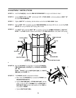
Page 15: ...ocks up or the resistance of the fan increases after use To adjust the fan use the following procedures It is best to lift the front of the frame and remove the fan and fan cages thru the bottom of the bike Remove both pedals Remove the SCREWS 52 54 and 55 holding the CHAIN GUARDS 29 30 and FAN CAGES 28 to the BIKE Remove the CHAIN GUARDS 29 30 HINT The CRANK 10 should be pointing down Remove the ...

Page 16: ...hould be able to spin freely on the FAN AXLE after completion of this step STEP 5 STEP 6 STEP 7 STEP 8 STEP 9 Reverse STEPS 1 through 4 to reinstall the FAN 18 FAN CAGES 28 CHAIN 17 and CHAIN GUARDS 29 30 NOTE DO NOT tighten NUTS 3 8 66 and NUTS M6 65 until STEP 11 The CHAIN must be adjusted as follows STEP 11 a b c Make sure the CHAIN 17 is on both the FRONT and REAR SPROCKETS Tighten NUT M6 65 o...

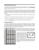
Page 17: ...IONING GUIDELINES 17 To maximize the benefits of exercising it is important to exercise with the proper intensity The proper intensity level can be found by using your heart rate as a guide For effective aerobic exercise your heart rate should be maintained at a level between 70 and 85 of your maximum heart rate as you exercise This is known as your target zone You can find your target zone in the...

Page 18: ...Your cool down should include the stretches listed above and should be completed after each strength training session Lower Body Stretch Place feet shoulder width apart and lean forward Keep this position for 30 seconds using the body as a natural weight to stretch the backs of the legs DO NOT BOUNCE When the pull on the back of the legs lessen try a lower position gradually Floor Stretch While si...

Page 19: ...t transferable IFANYPART OF THE PRODUCT ISNOT IN COMPLIANCE WITH THIS LIMITED WARRANTY OR ANY IMPLIED WARRANTY THE REMEDY OF REPAIR OR REPLACEMENT IS THE EXCLUSIVE REMEDYAVAILABLE TO YOU In the event that the purchaser makes any claim under this limited warranty or any implied warranty the Warrantor reserves the right to require the product to be returned for inspection at the purchaser s expense ...

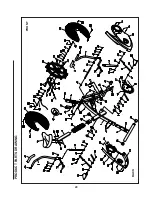
Page 20: ...PRODUCT PARTS DRAWING BACK FRONT 20 ...

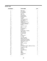
Page 21: ...h 1 18 Fan 1 19 Resistance Hub 1 20 Fan Bushing 2 21 FanAxle 1 22 Eye Bolt M6 x 1 x 50mm 2 23 Speed Pickup 1 24 Tension Spring 1 25 Tension Strap 1 26 Hook 1 27 Tension Knob 1 28 Fan Cage 2 29 Left Chain Guard 1 30 Right Chain Guard 1 31 Left Pedal w Long Shaft 1 32 Right Pedal w Long Shaft 1 33 Pedal Washer 1 2 2 34 Spacer 2 35 Thin Nut 1 2 20 2 36 Axle 1 37 Bushing 6 38 Bushing Washer M16 x ø25m...

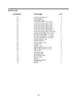
Page 22: ...ew Round Head M5 x 0 8 x 12mm 4 58 Screw Flat Head M5 x 0 8 x 15mm 1 59 Bolt Round Head M6 x 1 x 12mm 4 60 Bolt Round Head M6 x 1 x 25mm 4 61 Bolt Hex Head M8 x 1 25 x 45mm 2 62 Nylock Nut M8 x 1 25 7 63 Nylock Nut M6 x 1 4 64 Acorn Nut M8 x 1 25 2 65 Nut M6 x 1 2 66 Nut 3 8 26 5 67 Washer M8 x ø16mm x 1 5mm 3 68 Washer M8 x ø22mm x 1 5mm 2 69 Washer 3 8 3 70 Arc Washer M6 4 71 Arc Washer M8 4 72 ...

Page 23: ...part found please call 1 800 375 7520 in the U S between 8 00 A M and 5 00 P M Central Time Monday through Friday or fill out the fax sheet ordering form below and fax it to 417 889 8064 Our Customer Service Department will be able to assist you with your problem and the part will be mailed directly to your house TELEPHONE CUSTOMER SERVICE Tel 1 800 375 7520 FAX CUSTOMER SERVICE Fax 417 889 8064 M...

Reviews: