ASSEMBLY INSTRUCTIONS
8
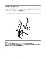
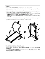
STEP 2
Place the
BASE FRAME(1)
between the
LEFT
and
RIGHT UPRIGHTS(2, 3)
and secure with
HEX
BOLTS(M12x1.75x75mm)(35)
and
WASHERS(M12)(45). DO NOT TIGHTEN COMPLETELY.
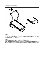
STEP 3
Slide down the upper parts of the
FOAM GRIPS(22),
so you can see the screw holes at the back side of the
tops of the
LEFT
and
RIGHT UPRIGHTS(2, 3).
Connect the
UPPER EXTENSION WIRE(26)
to the
LOWER
EXTENSION WIRE(27).
Insert the
U-SHAPED HANDRAIL(5)
into the
LEFT
and
RIGHT UPRIGHTS(2, 3)
and secure with
BUTTON HEAD BOLTS(M6x1x15mm)(36)
and
ARC WASHERS(M6)(41).
Slide up the
FOAM GRIPS(22)
to cover the screw heads.
STEP 4
Go back and tighten
HEX BOLTS(M12x1.75x75mm)(35)
in
STEP 2.
Connect the
LOWER EXTENSION
WIRE(27)
located on the
LEFT UPRIGHT(2)
to the
SENSOR WIRE(28).
Insert the
PULL PIN(6)
through
the
RIGHT UPRIGHT(3)
and
BASE FRAME(1)
to lock the
BASE FRAME(1)
in position.
Slide down the
upper parts of the
FOAM GRIPS(22)
for assembly.
Summary of Contents for In Motion T3000
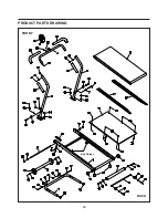
Page 14: ...PRODUCT PARTS DRAWING 14 FRONT BACK Belt Guides ...
Page 17: ...17 NOTES ...

