background image

OPERATIONAL INSTRUCTIONS

11

EXERCISE WORKOUT

To start using the 

InMotion® E3000

 simply stand on the foot pedals with the front of your shoes close to 

the front edge of the pedal cap. Move your highest foot forward and follow the natural path of the machine.

For more stability, hold on to the 

HANDLEBAR(72)


while stepping onto and off of the pedals. Start on a load 

level that is comfortable until you are familiar with the machine. Once you are familiar with the elliptical and 

comfortable with the resistance, adjust the load level as described below to achieve the workout desired.

FORWARD AND REVERSE

The 

InMotion® E3000

 can be used in forward and reverse directions to vary the muscles that you work. 

This will help you to stay motivated and achieve the best results. To change directions, simply slow the 

pedals down until they stop, then pedal in the opposite direction.

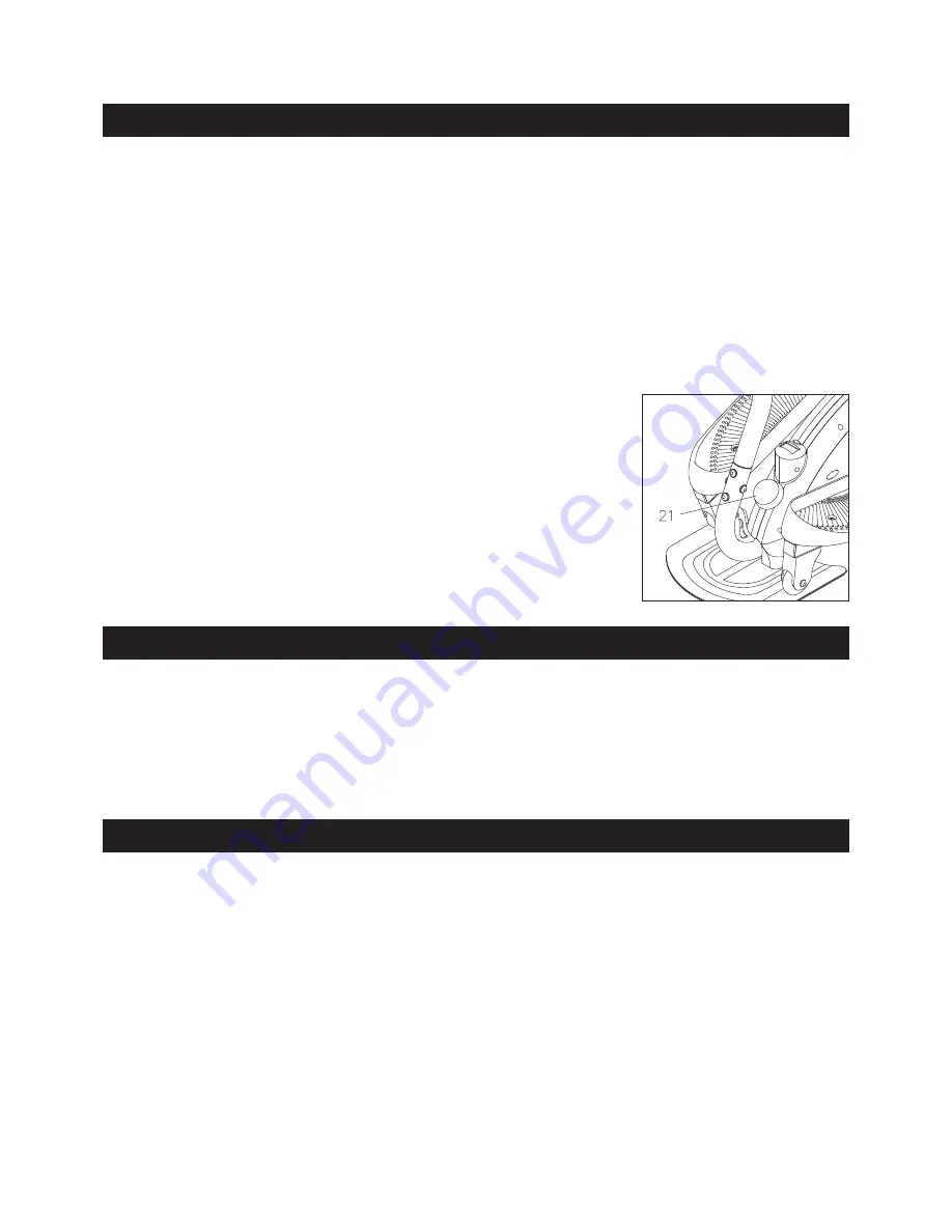
LOAD LEVEL ADJUSTMENT

The load level of 

InMotion® E3000

 can be changed at any time during 

your workout. Adjusting your load level will allow you to increase or 

decrease your intensity level.

To  increase  the  load,  turn  the 

TENSION  KNOB(21)

  clockwise.  To 

decrease the load, turn the 

TENSION KNOB(21)

 counterclockwise.

STORAGE

1.  To store the 

InMotion® E3000

 simply keep it in a clean dry place.

2.  The minimum rest dimensions of the 

InMotion® E3000

 are approximately 29.2 inches long x 18.5 inches 

wide x 45 inches tall. These dimensions may vary. Please measure your 

InMotion® E3000

 if exact 

dimensions are needed.

3.  Grasp the 

REAR STABILIZER(2)

 and 

HANDLEBAR(72)

 to move the 

InMotion® E3000

.

 Do not use 

the 

PEDAL ARMS(3,4)

 to move the 

InMotion® E3000

.

The  safety  and  integrity  designed  into  the 

InMotion® E3000

  can  only  be  maintained  when  the 

InMotion® E3000

 is regularly examined for damage and wear. Special attention should be given to the 

following:

MAINTENANCE

NOTE: 

A standard crank extractor tool is required to remove the 

CRANKS(28)

 from the 

AXLE(9).

1.  Adjust the 

TENSION KNOB(21)

 and verify that the Flywheel System provides tension. The Flywheel 

System should provide many years of use.

2.  Verify that the 

WARNING LABEL(55)

 is in place and easy to read. Call Stamina Products immediately 

at 

1-800-375-7520

 for a replacement 

WARNING LABEL(55)

 if it is missing or damaged.

3.  It is the sole responsibility of the user/owner to ensure that regular maintenance is performed.

4.  Worn or damaged components shall be replaced immediately or the 

InMotion® E3000

 removed from 

service until repair is made.

5.  Only Stamina Products supplied components shall be used to maintain/repair the 

InMotion® E3000

.

6.  Keep your 

InMotion® E3000

 clean by wiping it off with an absorbent cloth after use.

Summary of Contents for InMotion E3000

Page 1: ...lt a physician before beginning any exercise program with this equipment If you feel faint or dizzy immediately discontinue use of this equipment Serious bodily injury can occur if this equipment is n...

Page 2: ...and train within them Always use common sense when exercising 12 Do not wear loose or dangling clothing while using the InMotion E3000 13 Never exercise in bare feet or socks always wear correct foot...

Page 3: ...achieving a happier and healthier lifestyle Should you have any questions please call our Customer Service Department toll free number 1 800 375 7520 Monday Thursday 7 30 A M 5 00 P M Central Time Fr...

Page 4: ...constructs its products with the finest materials and uses the highest standards of manufacturing and quality control there can sometimes be missing parts or incorrectly sized parts If you have any qu...

Page 5: ...This chart is provided to help identify the warning and notice labels on the InMotion E3000 Please take a moment to familiarize yourself with all of the warning and notice labels EQUIPMENT WARNING NOT...

Page 6: ...e measured from the top of the head to the end of the bolt or screw length length After unpacking the unit open the hardware bag and make sure that you have all the following items Some hardware may b...

Page 7: ...minaproducts com ASSEMBLY INSTRUCTIONS 7 STEP 1 Attach the REAR STABILIZER 2 to the MAIN FRAME 1 with CARRIAGE BOLTS M10x1 5x43mm 42 and NYLOCK NUTS M10x1 5 51 STEP 2 Attach the BASE BOARD 37 to the M...

Page 8: ...adjustment holes on the HANDLEBAR POST 71 for adjusting the height of the HANDLEBAR 72 STEP 6 Refer to the detail view A Note the correct position of the HANDLEBAR 72 the HANDLEBAR 72 should be assem...

Page 9: ...wly through one complete revolution to verify that the drive train functions properly Adjust the TENSION KNOB 21 and verify that it functions properly CAUTION Locate and read the WARNING LABEL 55 on t...

Page 10: ...COUNT CALORIES FUNCTION BUTTON Press and release to select functions Press and hold for four seconds to reset all functions to zero Pedal movement or press the button The meter will shut off automatic...

Page 11: ...E3000 simply keep it in a clean dry place 2 The minimum rest dimensions of the InMotion E3000 are approximately 29 2 inches long x 18 5 inches wide x 45 inches tall These dimensions may vary Please me...

Page 12: ...of your maximum heart rate zone Start at the lower intensity and build up to higher intensity as you become more aerobically fit If you feel dizzy or lightheaded you should slow down or stop exercisin...

Page 13: ...cool down should include the stretches listed above and should be completed after each strength training session Lower Body Stretch Place feet shoulder width apart and lean forward Keep this position...

Page 14: ...PRODUCT PARTS DRAWING 14 FRONT BACK...

Page 15: ...nsor Wire 1 24 Magnet 1 25 Square Plug 25mm x 25mm 1 26 Left Cover 1 27 Right Cover 1 28 Crank 2 29 Flange Bolt M8 x 1 25 x 15mm 2 30 Crank Spacer 2 31 Large Washer 16 3 x 24mm 4 32 Pedal Arm Bushing...

Page 16: ...59 Bolt Button Head M8 x 1 25 x 16mm 6 60 Wavy Washer M17 1 61 C Ring 17mm 1 62 Pu Bushing 1 63 Square Plug 38mm x 38mm 1 64 Crank Cap 2 65 Large Tension Bracket 2 66 Double Eyebolt 1 67 Stabilizer S...

Page 17: ...ERY OF THE PRODUCT TO THE PURCHASER This limited warranty is not transferable IF ANY PART OF THE PRODUCT IS NOT IN COMPLIANCE WITH THIS LIMITED WARRANTY OR ANY IMPLIED WARRANTY THE REMEDY OF REPAIR OR...

Page 18: ...NOTES 18...

Page 19: ...tive part found please call us from 7 30 A M to 5 00 P M Central Time Monday through Thursday and 8 00 A M to 3 00 P M on Friday or fill out the fax sheet ordering form below and fax it to 417 889 806...

Reviews: