DE
13
EN
BEFORE FIRST USE
Upon receipt of the goods, check the packaging for integrity and open it. If the packaging is damaged, please
contact your transport company and distributor within 3 days, and document the damages as detailed as
possible. Do not turn the package upside down! When transporting the package, please ensure that it is
kept horizontal and stable. Please keep all packaging materials (cardboard, plastic tapes and styrofoam), so
that in case of a problem, the device can be sent back to the service centre in accurate condition.
Disposing of packaging
The various items used for packaging (cardboard, plastic straps, polyurethane foam) should be conserved,
so that the device can be sent back to the service centre in the best condition in case of any problems!
INSTALLING THE APPLIANCE
Appliance location
The work surface where the device will be located must be suitable for the size of the appliance, please re-
fer to the measurements. The work surface must be levelled, dry, heat-resistant and at a fitting height from
the ground to enable a proper use of the device.
The power cord connected to the appliance must be properly grounded and correspond to the technical
details.
Once the device is in place, remove the screw at the bottom. The screw is marked with red paint. In case
you need to transport the device, screw must be put back in the same place.
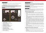
OPERATION – SOLDERING STATION ONLY
1.
Device must be placed on stable work table, soldering iron must be placed into the holder.
2.
Fix the appropriate soldering tip and connect the device to the power source.
3.
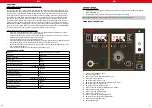
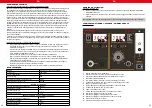
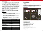
Turn on the device with the main switch placed at the back of the device, turn on the soldering iron
with switch (12), it will start to heat.
4.
Temperature setting: set the desired temperature using buttons (13). Working indicator (10) will glow.
When the soldering iron reaches the set temperature, indicator will flash quickly. When the tempera
-
ture drops, the indicator turns off.
5.
Soldering fumes absorption: soldering iron is equipped with soldering fumes absorption pipe. Absorp-
tion can be turned on with switch (3), smoke suction power can be controlled by the knob (1). It is
recommended to carry out regular inspection and replacement of the smoke absorber filter, which
is located on the front panel under the smoke absorber tube nut (16). The absorber is designed for
solder fume extraction only and may not be used for other purposes.
6.
The device can optionally be equipped with vacuum suction pen (with air hose and suction tips)
designed for displacement of the SMD elements when soldering. In order to use this vacuum suction
pen, air hose must be connected to the smoke absorber socket (16). Suction power can be adjusted
by knob (1).
7.
After work, the soldering iron should be placed into the holder. Turn off the soldering station by
switch (12).
8.
If the device is not used for a long time, it should be completely disconnected from the power source.
OPERATION – SMD REWORK STATION ONLY
1. Device must be placed on stable work table, SMD rework gun must be placed into the holder.
2. Fix the appropriate nozzle and connect the device to the power source.
3. Turn on the device with the main switch placed at the back of the device, turn on the SMD rework
gun with switch (5), gun is ready to work.
EN
4. Temperature setting: set the desired temperature using buttons (14). Working indicator (7) will
glow. When the SMD rework gun reaches the set temperature, indicator will flash quickly. When the
temperature drops, the indicator turns off.
5. Airflow volume adjustment: set the desired airflow volume with knob (1). The volume will be visible
on the indicator (4).
6. After work, the SMD rework gun should be placed into the holder. Turn off the SMD rework by
switch (5).
7. If the device is not used for a long time, it should be completely disconnected from the power source.
CHANGING THE TEMPERATURE UNIT (CELSIUS / FAHRENHEIT):
Turn on the soldering station and SMD rework station (or only one of them).Press buttons (13 - temperature
increasing button) and (14 - temperature decreasing button) simultaneously for about 3 seconds, the
⁰
C or
⁰
F will be flashing on the display. Set the desired unit using buttons (13) and (14). Chosen unit will be shown
on the display.
SETTING THE SOLDERING IRON AND SMD REWORK GUN TEMPERATURE COM-
PENSATION
Entering into temperature compensation setting mode: when both stations are turned on (switches 5 and
12 turned on), press simultaneously buttons (13 - temperature decreasing button) and (14 - temperature
increasing button) for about 3 seconds. Both displays will show “00”. Using buttons (13) set the desired
temperature compensation for soldering iron. Using buttons (14) set the desired temperature compensation
for SMD rework gun. The range of the compensation is from -50 to +50⁰C. After setting, device will
remember entered parameters and starts working after approx. 5 seconds.
GENERAL REMARKS
1. If the display is showing the „---„ it means that the output temperature is lower than 100 ⁰C, HOT
AIR station is in stand by mode, HOT AIR gun is placed in the holder.
2. If the display is showing “S-E” it means that soldering iron is disconnected, and HOT AIR gun is having
problem with the heat sensor.
3. When the device is being turned on, both soldering iron and HOT AIR gun should be placed in their
holders.
4. The outlet of the HOT AIR gun should be clean and free from any obstacles.
5. When using small nozzles, it should be remembered that the air flow should be suitable to the diame
-
ter of the fixed nozzle. In order to avoid any HOT AIR gun damages, too high air flow along with the
high temperature mustn’t be used for a long period of time.
6. Depending on user’s needs, different air flow settings may cause slight variations in temperatures va
-
lue. The minimum distance between the outlet of the HOT AIR gun and the subject is 2 mm.
7. Good ventilation of the room in which the appliance is used must be provided. In addition, the device
should be placed in a location with good air circulation to dissipate heat.
12
Summary of Contents for 6132 S-LS-16
Page 23: ...44...


