DE
13
EN
INSTALLING THE APPLIANCE
Appliance location
The work surface where the device will be located must be suitable for the size of the appliance, please
refer to the measurements. The work surface must be levelled, dry, heat-resistant and at a fitting height
from the ground to enable a proper use of the device.
The power cord connected to the appliance must be properly grounded and correspond to the technical
details.
OPERATION – SOLDERING STATION ONLY
1.
Device must be placed on a stable work table, soldering iron must be placed into the holder.
2.
Fix the appropriate soldering tip and connect the device to the power source.
3.
Turn on the device with the main switch placed at the back of the device, turn on the soldering iron
with switch (8), it will start to heat.
4.
Temperature setting: set the desired temperature using knob (6). Working (heating) indicator (11)
will glow. When the soldering iron reaches the set temperature, indicator will flash quickly. When the
temperature drops, the indicator turns off.
5.
After work, the soldering iron should be placed into the holder. Turn off the soldering station by
switch (8).
6.
If the device is not used for a long time, it should be completely disconnected from the power source.
OPERATION – SMD REWORK STATION ONLY
1.
Device must be placed on stable work table, SMD rework gun must be placed into the holder.
2.
Fix the appropriate nozzle and connect the device to the power source.
3.
Turn on the device with the main switch placed at the back of the device, turn on the SMD rework
gun with switch (7), gun is ready to work.
4.
Temperature setting: set the desired temperature using knob (5). Working (heating) indicator (9) and
working indicator (4) will glow. When the SMD rework gun reaches the set temperature, indicator (9)
will flash quickly. When the temperature drops, the indicator (9) turns off. Working indicator (4) will
glow as long as the SMD rework gun will be turned on.
5.
Airflow volume adjustment: set the desired airflow volume with knob (3).
6.
Setting the automatic (AUTO) or manual (MANUAL) SMD rework gun working mode: switching
between modes: set the switch (13) in the appropriate mode. In manual mode, SMD rework gun
working continuously. In automatic mode, SMD rework gun turns off when placed into the holder.
7.
After work, the SMD rework gun should be placed into the holder. Turn off the SMD rework by
switch (7).
8.
If the device is not used for a long time, it should be completely disconnected from the power source.
EN
6. Depending on user’s needs, different air flow settings may cause slight variations in temperature
values. The minimum distance between the outlet of the HOT AIR gun and the subject is 2 mm.
7. Good ventilation of the room in which the appliance is used must be provided. In addition, the device
should be placed in a location with good air circulation to dissipate heat.
SAFETY ISSUES REMARKS
1. Nozzles should be installed without the use of excessive force, also do not use the pliers or tweezers.
Do not tighten the mounting screws of the nozzle too much.
2. Tips and nozzles can be changed when the HOT AIR gun and the soldering iron are completely cold.
3.
It is forbidden to use the device near flammable or combustible elements and objects or in
similar places. Tips and nozzles as well as the air coming out of the HOT AIR gun have very high
temperatures, it is forbidden to touch these elements as well as it is forbidden to direct the hot air
directly to face or body. This can cause serious burns.
4. After long time of use, the outlet of the HOT AIR gun may be covered with some dust. The outlet
should be cleaned on a regular basis in order to ensure undisturbed air flow.
5. Too high temperature of the soldering iron may be the cause of reduction of the functionality of the
soldering tips.
6. Soldering iron tip must be cleaned regularly using sponge and plate on a layer of tin to prevent tips
oxidation.
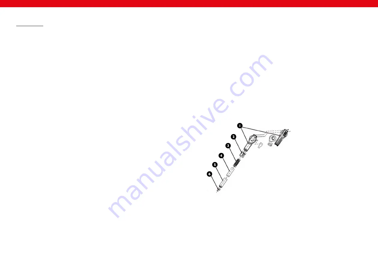
REPLACEMENT OF HOT AIR REWORK HEATING ELEMENT
1. HOT AIR gun covers
2. element of the handle
3. heater
4. heater cover
5. outlet pipe
6. nozzle
12
GENERAL REMARKS
1. If the display is showing „---„ it means that the output temperature is lower than 100
⁰
C, HOT AIR
station is in stand by mode, HOT AIR gun is placed in the holder.
2. If the display is showing “S-E” it means that soldering iron is disconnected, and HOT AIR gun is having
a problem with the heat sensor.
3. When the device is being turned on, both soldering iron and HOT AIR gun should be placed in their
holders.
4. The outlet of the HOT AIR gun should be clean and free from any obstacles.
5. When using small nozzles, it should be remembered that the air flow should be suitable to the
diameter of the fixed nozzle. In order to avoid any HOT AIR gun damages, too high air flow along
with the high temperature mustn’t be used for a long period of time.
1.
Before heater replacement, make sure that the SMD rework gun is completely cold.
2.
Remove the screws in the gun covers.
3.
Unscrew the element of the handle (2) and take off the gun covers.
4.
Gently remove the fan and remove the wire board screws.
5.
Disconnect the heater from the wire board (pay attention to the wires connection order).
6.
Remove the heater from the housing, pay attention to the steel grounding wire.
7.
New heater should be wrapped with new mica paper and then it should be placed inside the housing.
8.
Connect the wires to the board in accordance with their original connection method.
9.
Fix the gun in reverse order.


