background image

11SOLO2 User’s Manual                                             Revision 0.9


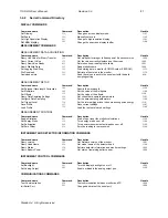
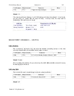
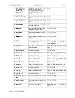
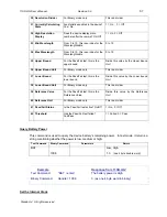
43 

3p 2 

3 picowatts or picojoules 

10p 3 

10 picowatts or picojoules 

30p 4 

30 picowatts or picojoules 

100p 5 

100 picowatts or picojoules 

300p 6 

300 picowatts or picojoules 

1n 7 

1 nanowatt or nanojoule 

3n 8 

3 nanowatts or nanojoules 

10n 9 

10 nanowatts or nanojoules 

30n 10 

30 nanowatts or nanojoules 

100n 11 

100 nanowatts or nanojoules 

300n 12 

300 nanowatts or nanojoules 

1u 13 

1 microwatt or microjoule 

3u 14 

3 microwatts or microjoules 

10u 15 

10 microwatts or microjoules 

30u 16 

30 microwatts or microjoules 

100u 17 

100 microwatts or microjoules 

300u 18 

300 microwatts or microjoules 

1m 19 

1 milliwatt or millijoule 

3m 20 

3 milliwatts or millijoules 

10m 21 

10 milliwatts or millijoules 

30m 22 

30 milliwatts or millijoules 

100m 23 

100 milliwatts or millijoules 

300m 24 

300 milliwatts or millijoules 

1 25 

1 Watt or Joule 

3 26 

3 watts or joules 

10 27 

10 watts or joules 

30 28 

30 watts or joules 

100 29 

100 watts or joules 

300 30 

300 watts or joules 

1k 31 

1 kilowatt or kilojoule 

3k 32 

3 kilowatts or kilojoules 

10k 33 

10 kilowatts or kilojoules 

30k 34 

30 kilowatts or kilojoules 

100k 35 

100 kilowatts or kilojoules 

300k 36 

300 kilowatts or kilojoules 

1meg 37 

1 megawatt or megajoule 

3meg 38 

3 megawatts or megajoules 

10meg 39 

10 megawatts or megajoules 

30meg 40 

30 megawatts or megajoules 

100meg 41 

100 megawatts or megajoules 

300meg 42 

300 megawatts or megajoules 


 Standa Ltd.  All rights reserved 

Summary of Contents for 11SOLO2

Page 1: ...SINGLE CHANNEL LASER POWER ENERGY METER 11SOLO2 INSTRUCTION MANUAL Revision 0 9 June 2008 ...

Page 2: ...ranty In case of malfunction contact your local Standa distributor or nearest Standa office to obtain a return authorization number The material should be returned to STANDA Švitrigailos 4 39 03222 Vilnius Lithuania Tel 370 5 2651474 Fax 370 5 2651483 e mail sales standa lt Website www standa lt CLAIMS To obtain warranty service contact your nearest Standa agent or send the product with a descript...

Page 3: ... not installed and used in accordance with the instructions may cause harmful interference to radio communications However there is no guarantee that interference will not occur in a particular installation If this equipment does cause harmful interference to radio or television reception which can be determined by turning the equipment off and on it is suggested to try to correct the interference...

Page 4: ... 3 3 5 Period Multiplier 29 2 3 3 6 Refer Values 29 2 3 3 7 Save and Load User Settings 30 2 3 3 8 Power Unit 31 2 3 3 9 Communication 31 2 3 3 10 Fluence 31 2 3 3 11 Peak Power 31 2 4 REAL TIME CONTROLS AND ABOUT 11SOLO2 31 2 4 1 Control Functions in the Ctrl menu 32 2 4 1 1 Ctrl Zero Offset 32 2 4 1 2 Ctrl Acquire Data 32 2 4 1 3 Ctrl Transfer File 32 2 4 1 4 Ctrl Statistics Mode 33 2 4 1 5 Ctrl...

Page 5: ...ctory 41 3 4 3 Serial commands 42 3 4 4 ERROR MESSAGES 60 4 1 USB INSTALLATION FOR THE SOLO2 61 4 2 FREE SOFTWARE UPGRADE 61 4 3 BATTERY CHARGING 61 QEA AND QEAS 62 5 1 QEA 12 25 50 AND QEAS 12 25 50 62 ATTENUATOR DIFFUSER CALIBRATION PROCEDURE 62 6 APPENDIX B 64 6 1 RECYCLING AND SEPARATION PROCEDURE 64 6 2 SEPARATION 64 6 3 DISMANTLING PROCEDURE 64 Standa Ltd All rights reserved ...
Page 6: ...SPLAY OPTIONS MENU 17 FIG 2 6 STATISTICS DISPLAY 18 FIG 2 7 STATUS DISPLAY 19 FIG 2 8 WATTMETER DATA SAMPLING MENU 19 FIG 2 9 VIEW FILE SCREEN 20 FIG 2 8 DIGITAL NEEDLE DISPLAY 21 FIG 2 10 SCALE MENU 21 FIG 2 11 SETTINGS MENU 22 FIG 2 12 SETTING CORRECTION MENU 23 FIG 2 13 DATA SAMPLING PARAMETERS WINDOW 26 FIG 2 14 PASS FAIL MENU 30 FIG 2 15 PULSE WIDTH SETTING FOR THE PEAK POWER MODE 31 FIG 2 16...

Page 7: ...detector heads for heads version 4 and above The 11SOLO2 is already internally set up to accept all the Standa wattmeter and joulemeter heads with a DB 15 connector When connecting a 11QE xx x MT or a 11XLE 4 the 11SOLO2 enters in the metallic mode to ensure proper measurements The metallic mode is available on all 11SOLO2 The new 11SOLO2 also has improved performance in joulemeter mode that allow...

Page 8: ...Statistics Current value Max Min Average Std Dev RMS stability PTP stability Time Energy meter specifications 11SOLO2 Energy Range 0 1µJ to 20 kJ Energy Scales 20 scales 10uJ 30uJ 100µJ 300µJ 1mJ 3mJ 10mJ 30mJ 100mJ 300mJ 1J 3J 10J 30J 100J 300J 1kJ 3kJ 10kJ 30kJ Resolution digital 5 nJ Accuracy3 1 0 50 µV 500 Hz 2 0 50 µV 500 Hz to 1 2 kHz 3 50 µV 1 2 kHz to 6 kHz MT mode 6 50 µV 6kHz to 10 kHz M...

Page 9: ... multipliers and 2 offsets 7 digits floating point Analog Output 0 1 volt full scale 1 Internet Upgrades USB and RS 2326 PC Serial Commands USB and RS 2325 High throughput serial frequency Up to 200Hz with a 310 ms delay between burst for Metallic or XLE joulemeters whereas 45 to 78 ms for MB joulemeter and power heads Dimensions without stand 210 mm W x 122 mm H x 44 mm D Weight with stand 0 52 k...

Page 10: ...r OFF If you are working without the external power supply turn the backlight off for longer battery life 2 Arrow keys a The Arrow keys allow the user to browse through the menus Press the Right Arrow key until you reach your desired option To go backwards keep pressing the Left Arrow key b When you are not in the Menu the Arrow keys permits alternative function for quick access button UP key Make...

Page 11: ...Down arrow keys to decrease and increase the LCD screen contrast 1 4 Top Panel Description Fig 1 2 11SOLO2 Top Panel 1 EXTERNAL POWER SUPPLY INPUT JACK CAUTION Permanent damage may occur to the optical meter if an external power supply other than the Standa P N 200960A is used Please call Standa or your local distributor if extra power supplies are needed Input voltage required 9 VDC 800 mA For an...

Page 12: ...orresponds to 30 milliwatts on the 300 mW range Specifications Maximum output voltage 1 V Output impedance 10 kΩ Connector type Female 1 8 jack 5 PROBE INPUT JACK The 11SOLO2 uses a DB 15 female connector to mate with the detector heads probes The 11SOLO2 works with all Standa detectors It automatically recognizes every power detector head which ensures accurate auto calibration More importantly i...

Page 13: ... menus The powerful CPU of the 11SOLO2 combined with the Windows CE operating system provides easy and intuitive access to all of its functions This user friendly Windows based interface is controlled by four Arrow keys an key Enter key and a Menu key For users familiar with Windows it works as any Windows menu with the ALT key being replaced by the F key Pressing the F key see Figure 2 1 provides...

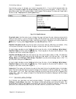
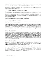
Page 14: ...log menu Use the Decimal button to enter decimals The Percent button gives you the flexibility to enter a value as a percent rather than a fraction For example you can enter the same multiplier as 0 925 or 92 5 Sensitivity V J 200 00 7 8 9 OK X 4 5 6 1 2 3 0 Fig 2 2 The dialog box 2 2 Quick power and energy measurement procedure This section applies to all 11SOLO2 versions It will show you the fas...

Page 15: ...over Put the detector head into the laser beam path Leave it there for a few minutes until the detector has reach an equilibrium temperature The entire laser beam must be within the sensor aperture Do not exceed maximum specified densities energies or powers For the most accurate measurement spread the beam across 60 to 80 of the sensor area Attention Power heads can be used with both CW and pulse...

Page 16: ...e 11SOLO2 Do not touch the detector head when handling the power detector Touch only the stand Avoid forced airflow or drafts around the detector 11 Apply the laser beam to the detector head 12 The laser beam average power or energy will be displayed in three ways for your convenience a Digitally for real time measure b On a digital needle for an easy visualization of the laser beam power variatio...

Page 17: ...interfering with the measurements 2 3 1 1 Real time display This display is automatically selected when a head is connected to the 11SOLO2 The top and bottom of the screen shows important settings so you see the conditions as well as the measurement see Figure 2 4 The Power or Energy Digital display is presented in giant format for easy reading in all conditions Directly below the Bargraph display...

Page 18: ...2 3 1 2 Histogram display The histogram option gives a quick look at the laser beam s long term stability and trends The histogram adds new data points at a rate of 3 Hz and is dynamically scrolled to the left for each new point as soon as it reaches the right side of the screen Display Scale Settings Ctrl Real Time View File Histogram Fluence Line Plot Avg Power Statistics Zoom Peak Power Tuning ...

Page 19: ...uted The data sampling and statistical calculations continue with this window closed or open and no matter what display you select You can open and close the statistics display window to check on the statistics as often as you like The values in this display provide an additional digit of resolution to allow you to benefit from the improved precision of large samples You must understand your sampl...

Page 20: ...s run in the background in this mode This mode is a real time average of a group of data defined in the data sampling setting For optimum averaging when measuring the average power of a pulsing laser it is preferable to use a sample period that is a multiple of your laser repetition rate For instance if you are running at 1 Hz use a sample period of 1 2 3 etc seconds If it is at 1 5 Hz use 3 6 9 e...

Page 21: ...cquired Choose between standard Std notation and scientific Sci notation Fig 2 9 View File screen 2 3 1 9 Fluence Display In the Fluence display mode the energy or power measurement is converted into energy density J cm2 or a power density watts cm2 and is inversely proportional to the surface area of the beam This function is active in the energy and power modes The user must enter the beam size ...

Page 22: ... display 2 3 2 Scale Menu The Scale menu The scale can be set in the automatic scaling mode auto mode or you can choose a specific fixed scale according to the specific head using the arrow keys on the keyboard However once the Standa head has been automatically identified from the detector head s EEPROM the only scale menu available is the one corresponding to the detector head connected to the 1...

Page 23: ...cs that require you to multiply and or add offsets to the detector reading You can also adjust for a wavelength other than the calibration wavelength A custom correction factor can also be keyed in Pre programmed wavelength correction factors dedicated to each detector head are also available and automatically loaded from the detector EEPROM for the version 5 and higher detector heads Data samplin...

Page 24: ...ns menu to manually enter a multiplier to correct for the wavelength You will find these multipliers on the Personal wavelength correction Certificate shipped with the detector You can use both the Wavelength menu and the Corrections menu for all V5 and later detectors 2 3 3 2 Corrections Setting The user can apply up to 2 multipliers and 2 offsets to the detector reading Correction factors are mo...

Page 25: ...ling parameters for calculating the Statistics You have complete control over the data sampling Use the defaults or select your own sample rate sample period and the time period or number of points to do the statistics You can set the 11SOLO2 either to calculate the statistics for a single sample and stop or to repeat continuously Take data for a few seconds or a few weeks You have the flexibility...

Page 26: ...cs mode off When you stop the statistics the last values remain in the statistics display window for you to view later If you click start again the 11SOLO2 will resume the statistics from that point compiling the new measurements with the previous Click Reset and all the statistical parameters will be cleared and set to zero If you click Reset without stopping all the statistical parameters will b...

Page 27: ...ble 2 2 defines the various parameters The key points to remember whether using a joulemeter or wattmeter are Sample Rate Controls how fast you collect data Eg 10 points second or 50 of pulses Sample Period Controls how much data the statistics are computed for Eg 5 minute or 1 day averages Total Duration Controls how long the SOLO2 will acquire data and or do statistics Eg 1 period 5 hours or 100...

Page 28: ... of samples used in the average and standard deviation for example for each average to be based on 5 minutes of data set to 5 minutes This is also the time period displayed by the Histogram and Line plot 10 Power 500 Energy Sample period units Second Minute Hour Day Week Pulses Sets the time period for the value entered above Maximum is 300 weeks or 100 000 pulses Minimum is 1 second or 1 pulse Mi...

Page 29: ...he UP arrow adds units while the DOWN arrow subtracts units To return to the Time dialog box press the Menu key Set Time To set the time use the right and left arrow keys to select the time hours or minutes using the 24 hour clock The UP arrow adds units while the DOWN arrow subtracts units Press the Enter key to validate the selection 11SOLO2 time will remain as long as the battery lasts To save ...

Page 30: ...rying energy values in the Autoscale mode The Autoscale function uses the energy level of the last pulse to set the scale level Therefore it will not detect the next pulses if they are lower than the trigger level As a result the Autoscale may become caught on a high scale value To solve this problem select a lower value for the trig level change the scale manually or reset the autoscale by resele...

Page 31: ...fail if the current power triggers it Pass Fail Full Display mode Use this mode to see if the current power passes or fails The default is pass If the current power rises above the threshold or falls below it you will see fail In the Full Display Mode select Settings Refer Values Pass Fail to see the screen display pass or fail To get to the Menu Bar press the Menu key To reset a failed experiment...

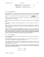
Page 32: ...watts per square centimeter watts cm2 Using this setting the user must enter the surface area of the beam at the detector surface in square centimeters or enter the beam diameter in centimeters for a round beam 2 3 3 11 Peak Power In energy mode the Peak Power display mode is used to convert a pulse energy measurement to its peak power value in watts The user must enter the pulse width Units from ...

Page 33: ...m to ensure accurate measurements For instructions on the proper way to adjust the offset to zero your detector see steps 8 10 in Section 2 2 Quick power and energy measurement procedure This control is only available for power meters 2 4 1 2 Ctrl Acquire Data When you select Start the 11SOLO2 begins storing data according to your Data Sampling settings see section 2 3 3 3 and Table 2 2 Those sett...

Page 34: ...tion 3 3 2 4 1 4 Ctrl Statistics Mode Use this option to activate the statistics computations Select Start in the submenu and the 11SOLO2 will start compiling statistics Select Stop in the same submenu to turn the Statistics mode off When you stop the statistics the last values remain in the statistics display window for you to view later If you click start again the 11SOLO2 will resume the statis...

Page 35: ... uncertainty in the power measurement typically 2 5 because the energy calibration is computed from the power measurement calibration A precision of 3 in the single pulse energy measurement can be achieved if the power detector head is specifically calibrated to measure in single pulse energy mode Please contact your local Standa distributor or nearest Standa office for more information on obtaini...

Page 36: ... on 2 4 1 9 Ctrl Display Hi Res This menu item is a toggle switch that turns on and off a higher precision display mode It will increase the value displayed numerically on the screen by one significant digit especially for relative changes in power or energy Absolute accuracy depends on the head 2 4 1 10 Ctrl View Data Use view data to transfer a file in the notation you would like to see it in sc...

Page 37: ...ich are available on our web site They do not support Windows VISTA At the end of this process a new serial COM port will be added to the list of communication ports It may be used as any other serial port See the Installation PDF to verify or change the COM port assignment You will need to know the COM port number to set up the serial connection to the 11SOLO2 Note Although the 11SOLO2 is equippe...

Page 38: ...d and ready for serial command action 3 2 5 HyperTerminal settings shortcut When you end the session HyperTerminal asks if you want to save your settings To avoid inputting the communication parameters again in the future save by clicking Yes The next time you execute the string of commands shown in section 3 2 2 above the name of your session will appear after HyperTerminal Clicking on the sessio...

Page 39: ...ut command the 11SOLO2 sends an acknowledgement of the command to the host device under the form of a short message describing the change that has been made 3 4 1 Serial Command format 3 4 1 1 Serial Protocol Rules Commands can be sent as text strings OR numerical values text mode binary mode The device automatically recognizes whether the received data is a text command or a binary command You ar...

Page 40: ... can program the commands in decimal for sending from the PC The 11SOLO2 send data in big endian format that is the most significant byte comes first You may need to convert to little endian depending on the software and computer you are using Binary command example backlight ON Command Parameter Text mode BKL 1 Binary mode in decimal 1003 1 2 byte word 4 byte word Byte 1st 2nd 1st 2nd 3rd 4th in ...

Page 41: ...e value for the Backlight command to Handle ParameterA 1 Assign to value for ON to the variable ParameterA SendStringToSerialPort PackedData 6 This routine transfers the data found at the address of structure PackedData to the serial port 6 bytes used Standa Ltd All rights reserved ...

Page 42: ...129 Query Data Sampling Settings RDS Get current data sampling parameters 1151 Configure Data Sampling DSU Set the data sampling parameters 1152 Set Trigger Level TLA Set the internal trigger level when measuring pulse energy 1112 Save Profile SVP Save current settings 1141 Load Profile LDP Load the last set of saved settings 1142 MEASUREMENT CONTROL Command name Command Description Handle Enable ...

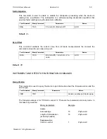
Page 43: ... screen display mode Text Command Binary Command Parameters Return SDU 1157 Display Mode ACK Available display modes Parameter 0 Real Time Display Default display mode It shows the current measured value 1 Histogram Shows a short history of the acquired data Statistic 2 Shows all data relevant to statistics 3 Digital Needle Provides a simulated analog needle Set Scale This command is used to force...

Page 44: ...oules 1m 19 1 milliwatt or millijoule 3m 20 3 milliwatts or millijoules 10m 21 10 milliwatts or millijoules 30m 22 30 milliwatts or millijoules 100m 23 100 milliwatts or millijoules 300m 24 300 milliwatts or millijoules 1 25 1 Watt or Joule 3 26 3 watts or joules 10 27 10 watts or joules 30 28 30 watts or joules 100 29 100 watts or joules 300 30 300 watts or joules 1k 31 1 kilowatt or kilojoule 3k...

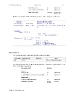
Page 45: ...urn On 0 to turn Off ACK Default Off MEASUREMENT COMMANDS DATA ACQUISITION Query Current Value This command is used to query the value that is currently being displayed on the device s screen The value is displayed in watts or in joules Text Command Binary Command Parameters Return CVU 1200 Current value For example a 12 milliwatts reading would be displayed like this Current Value 0 012 In binary...

Page 46: ...ated since the last query Query Statistic Data This command is used to read all the statistics data provided that the device has previously been set into statistic mode Text Command Binary Command Parameters Return VSU 1202 Statistics In text mode all the data and relevant identifiers are formatted into a tab separated string In binary mode the following structure is sent Statistics Current Value ...

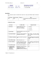
Page 47: ...and Parameters Return LOG 1171 0 to Stop 1 2 or 3 to Start ACK This command begins or stops logging data in the device s volatile memory This is done using the Data Sampling settings sample rate time period If you do not want to use the Data Sampling default settings you must use the DSU command prior to this one or set the Data Sampling settings manually on the monitor Passing 0 as parameter stop...

Page 48: ...t of record 0 Raw Value 1 Time Stamp Raw Value 2 average max value min value ptp stability RMS stability standard deviation 3 average max value min value ptp stability RMS stability standard deviation average power The following example is for a file 400 bytes long with timestamps and containing a 20 char text header Example Response from 11SOLO2 Text Command FDL enter File 0 data EOF LF Binary Co...

Page 49: ...and is used to adjust the processing of the monitor with the readings of the head depending if the head is using an external attenuator or not Text Command Binary Command Parameters Return ATU 1162 1 to turn On 0 to turn Off ACK Default Off Set Multipliers This command is used to set the value of the multipliers Text Command Binary Command Parameters Return SMU 1128 Multiplier 1 or 2 Multiplier va...

Page 50: ...parameter 1 or 2 and entering a new value in the second parameter In binary mode an extra parameter is required the scale at witch the value is set This is to prevent any cross platform floating point conversion error The following example sets offset 1 1 5 milli Example Response from 11SOLO2 Text Command SOU 1 0 0015 enter ACK CR LF Binary Command Handle 1129 Parameter1 1 Parameter2 15 Parameter3...

Page 51: ... of the total duration of sampling or statistics Total Duration Unit 0 One Sample Period 1 Seconds 2 Minutes 3 Hours 4 Days 5 Weeks 6 Continuous loop when done 7 Predefined number of points Timestamp 0 Off 1 On Configure Data Sampling This command provides the data sampling parameters for the logging and statistics environments These settings are used when saving data on the device s data storage ...

Page 52: ...ks 6 Continuous 7 Predefined number of points May be a fixed amount of time or points one or many periods or non stop Timestamp 0 Off 1 On Adds a time stamp for all logged data in the sample The following example sets a single data acquisition run for 90 minutes with timestamps at 4 hertz Example Response from 11SOLO2 Text Command DSU 4 0 90 1 1 0 1 enter ACK CR LF Binary Command Handle 1152 ACK P...

Page 53: ... 15400 ACK MEASUREMENT COMMANDS CONTROL Enable Statistics This command is used start stop and reset the statistics calculating process on the data currently acquisitioned by the specified channel upper or lower Text Command Binary Command Parameters Return ESU 1155 0 1 or 2 to Disable Enable or Reset ACK Default Disable Prior to enabling the statistics the user should use the LG1 LG2 and LG3 comma...

Page 54: ... issued to set a new zero point Text Command Binary Command Parameters Return EOA 1120 0 to turn Off 1 to turn On 2 to undo ACK Default Off INSTRUMENT AND DETECTOR INFORMATION COMMANDS Query Version This command is used to query the device to get information about the firmware version and the device type Text Command Binary Command Parameters Return VER 1001 Version number and device type The foll...

Page 55: ...arameters 0 0 0 1 0 0 0 2 0 0 0 4 83 79 76 79 0 0 0 1 version 1 0 0 0 2 extension 2 0 0 0 4 4 characters coming 83 79 76 79 ASCII code for SOLO2 Query Head Name This command is used to query the model name of the current head Text Command Binary Command Parameters Return HEA 1100 Name of the current heads The following example is an 11QE 25 SP MB joulemeter There are four parameters in binary mode...

Page 56: ...head same 3 Head Serial Number Alphanumeric string indicating the serial number for the head Size indicator The Serial number string is located at the end of the binary data 4 Calibration Sensitivity Sensitivity at default wavelength in V W This is specified in V W for the Default Wavelength Divide this value by 100000 5 Default Wavelength Default Wavelength in nm same 6 Active Sensitivity Current...

Page 57: ...his value by 1000 17 Zero Offset Currently used offset see Zero Offset command Divide this value by the Zero Offset Unit 18 Zero Offset Unit For Binary mode only This is a divider 19 Multiplier 1 Value of the first multiplier Divide this value by the Mult 1 Unit 20 Mult 1 Unit For Binary mode only This is a divider 21 Offset 1 Value of the first offset Divide this value by the Offset 1 Unit 22 Off...

Page 58: ...r bound Divide this value by the Lower bound Unit 38 Lower Bound Unit For Binary mode only This is a divider 39 Reference Value For the Pass Fail test this is the Reference Value Divide this value by the Reference Unit 40 Reference Unit For Binary mode only This is a divider Is the Pass Fail test active On Off 41 Pass Fail Status 1 On 0 Off 42 Threshold Has the Pass Fail test failed Fail Pass 1 Fa...

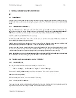
Page 59: ... is assumed if over 12 Minute 0 to 59 Second 0 to 59 AM PM 0 Am 1 PM INSTRUMENT CONTROL COMMANDS Set Backlight This command is used to turn the backlight of the device display on or off Text Command Binary Command Parameters Return BKL 1003 1 to turn On 0 to turn Off ACK Default Off Set Analog Output This command is used to enable or disable the output of the current value on the analog port of th...

Page 60: ...command is used to change the current baud rate of the serial port of the device Valid parameters are 2400 9600 14400 19200 38400 or 115200 Upon receipt of the command the device sends an acknowledgement and then closes and restarts the serial port at the new speed if the new baud rate is different from the current one You must also change the baud rate of your own serial port Text Command Binary ...

Page 61: ...ame connection for output and trigger at the same time 11 Anticipation is not available Make sure that the detector is in power reading mode 12 Statistics are not available Statistics must first be enabled 13 PWC is not available Make sure that the detector head version supports Personal Wavelength Correction 14 Invalid Command Too long The command must not be over 255 characters long 15 Too many ...

Page 62: ...y it will extract and start the Firmware Updater automatically You will set the 11SOLO2 in Update Mode by turning it off and holding the RIGHT arrow key while turning it on again Make sure that the correct COM port is selected in the Firmware Updater You can use the Test communication with device button to make sure that everything is well linked If the device is correctly connected to the compute...

Page 63: ...e Attenuator setting in the Control menu must not be checked That is it must be off Otherwise you cannot access the wavelength correction Settings Æ Corrections menus You need this to input the wavelength that you are calibrating at see monitor manual The Attenuator setting should also be checked off if you are redoing a calibration at the same wavelength stated on joulemeter calibration certifica...

Page 64: ...the calibration A change larger than the uncertainty of your measurements means that something in the laser or environment changed You can add this to your uncertainty when you use the attenuator or try to stabilize the laser and environment and begin again with Step 3 The correction multiplier for the revised 11DUO rev 2 0 the 11SOLO2 and an Oscilloscope will be given by attenuator with Reading a...

Page 65: ...uction manual 1 Calibration certificate 1 Software cdrom 6 2 Separation Paper Manual and certificate Plastic monitor enclosure LCd enclosure Wires USB cable and power supply plug NimH batteries inside the monitor Liquid crystal display Less than 100 cm2 Printed circuit board inside the monitor 6 3 Dismantling procedure Remove the DB15 post using pliers Remove the 4 screw on the bottom of the monit...

Reviews: