P.O. Box 2684
03001 Vilnius, Lithuania
Phone: +370-5-2651474
Fax: +370-5-2651483
E-mail: sales@standa.lt
Manufacturer of Opto-Mechanical equipment for research, industry and education
http://www.standa.lt
10
2.2 Preparation of the system for operation and vibration isolation of the table
2.2.1 Assembly of level controls
A level control is shown in fig. 2.
All systems, regardless of the number of pneumatic supports used in them, are provided with 3
level controls that form a triangle. The greater the triangle of a specific optical table is, the more stable
is the operation of the system. If 2 or more pneumatic supports are controlled by means of a single level
control, then they operate as one large support with the total load-carrying capacity applied to the centre
of the shape formed by the pneumatic supports. Groups of pneumatic supports serve as three supports
for the system. The aggregate centre of gravity of the optical table and of the useful load present on the
table must be within the boundaries of the triangle formed by force centres.
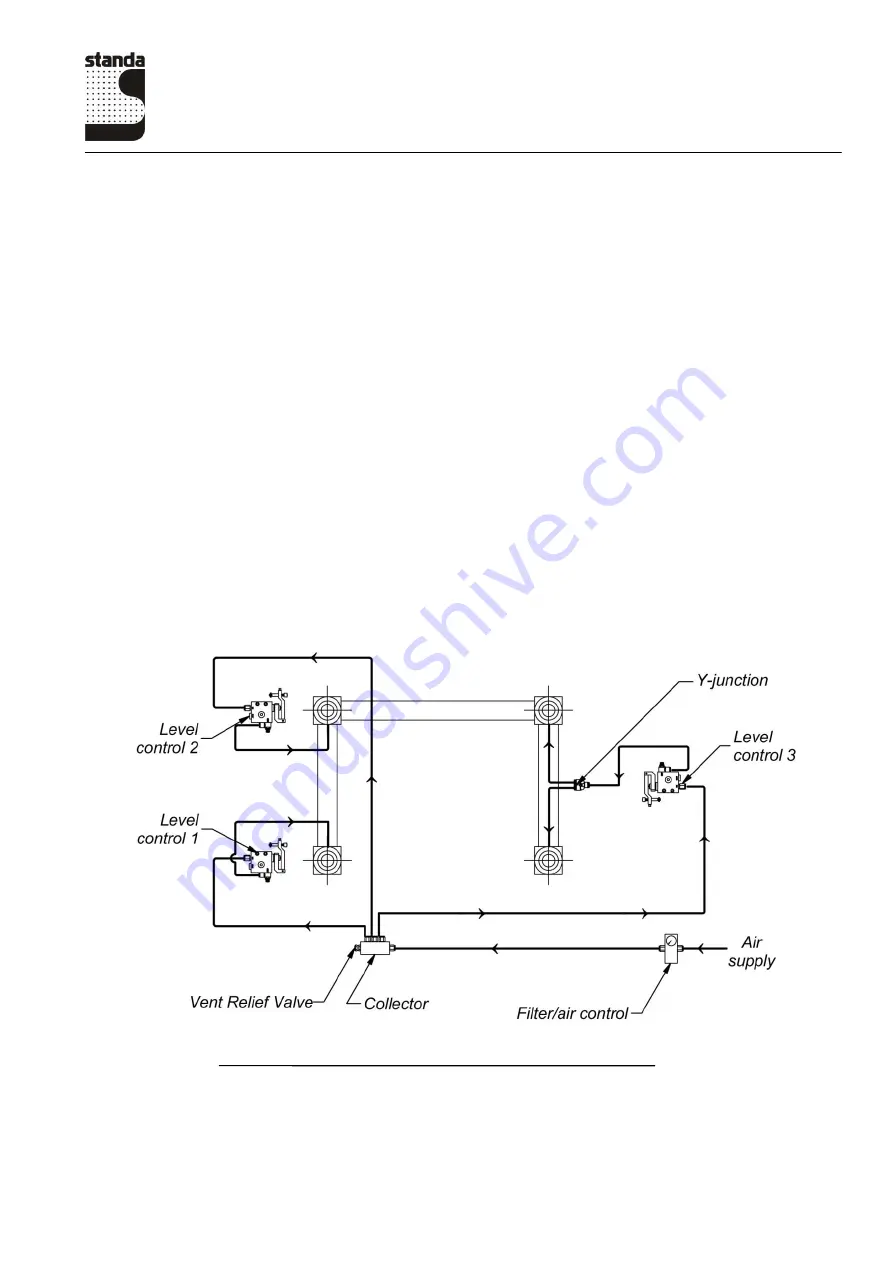
Scheme of connection of level controls is shown in fig. 8.
After placement of the table, level controls must be fastened to the supports as shown in fig. 9
and in fig. 10.
Attach the plate to the leg assembly by M5x10 screws.
Attach the level control to the plate by nut plate (fig.9).
Align the controls horizontally and set the distance from the bracket of the controls to the table at
10 to 11 mm. The control screw of the lever must be set to the bottom position. The needle valve must
be turned clockwise until it closes. Tighten the two mounting screws carefully.
Fig.8. Scheme of connection of level controls


