P.O. Box 2684
03001 Vilnius, Lithuania
Phone: +370-5-2651474
Fax: +370-5-2651483
E-mail: sales@standa.lt
Manufacturer of Opto-Mechanical equipment for research, industry and education
http://www.standa.lt
12
After placement of the three controls the system must look as shown in fig. 9.
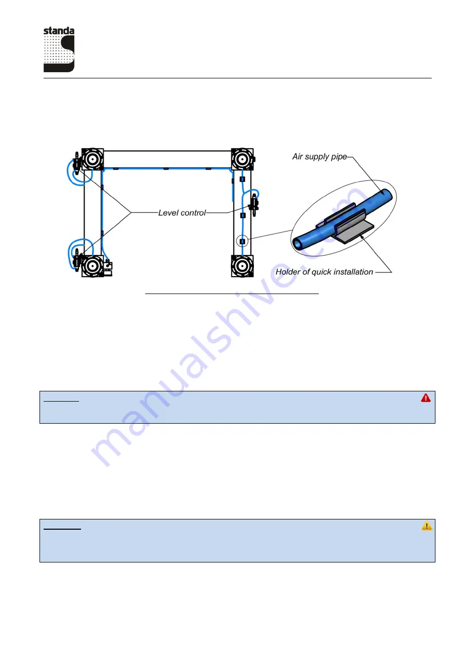
Fig. 11. Vibration isolation system
2.2.2 Connection of air supply pipes
Connect the air supply pipes as shown in fig. 8 as well as in the pneumatic connections scheme
that is supplied together with the system.
Warning
Cut the edges of the pipes using a sharp cutter at a straight angle. It is not advisable to use
scissors because deformation of the pipe edges may lead to leaks from the system.
Insert the pipes in the collet fittings until tight. Pull the pipes accurately to make sure that the
connection is secure.
The length of the pipes between the fittings must be optimal with a small extra length.
Place the tubes along the braces system and secure them with holders of quick installation (fig.
11)
Connect the air supply and set the pressure control based on the computation of its value carried
out in advance according to the formula provided in section 1.3.
Attention
The pressure in the system may not exceed 6 bar.
Check all accessible connections for possible leaks. Eliminate any leaks established prior to
starting further operation.
When the air starts to flow from the air supply to the pneumatic isolation system, open the needle
valves of the level controls.


