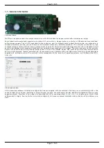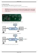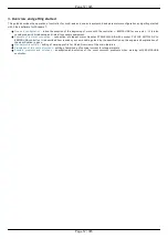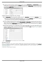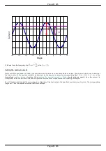
The motor controller board.
The controller appearance may differ from the one shown on the above figure depending on its configuration and version. For
detailed information about versions please read the
Appearance and connectors 8SMC5
chapter.
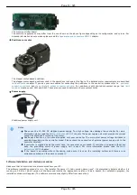
Positioner or motor
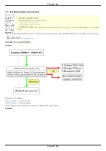
The stepper motor-based positioner.
The stepper motor-based positioner used in the operations is shown at the figure. The detailed motor requirements are described
in
chapter. If you use your own cables for connecting the positioner to the controller, please refer to
the controller's output connector scheme
. For positioners with limited movement range, two
must be used: SW1 and SW2. These pins are used to determine the movement limits.
Power supply
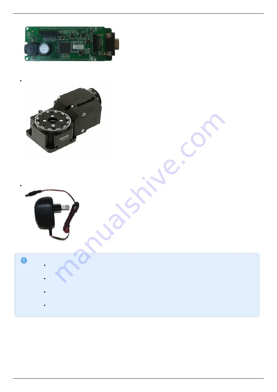
Stabilized power supply unit.
Notes.
Please use the 12–36V DC stabilized power supply. Too high voltage may damage the controller. For more
information please read the
chapter. The power supply unit must provide the current
enough for sustainable rotation of the motor.
Please pay attention on the manual supplied with your controller. The more strict power voltage limitation is
possible depending on the controller model. Please check the connection of external power supply unit to the
controller carefully.
If controller is supplied inside the metal case, the case must be grounded. If controller is supplied without any
body, the grounding circuit of power supply unit is used. For more information please read the
If the board is operated without the casing, make sure it lays on the insulating surface and there are no
extraneous particles on the board or around it.
Software installation and startup procedures
Make sure that all controllers are disconnected from your PC.
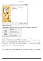
The software installation manual is
. The installer file name is "xilab-<version_name>.exe". It automatically detects whether it is
running on 32-bit or 64-bit version of Windows and installs the appropriate version of XiLab. Launch the installation program, the
installation window will appear. (The software versions may slightly differ from each other).
Page 14 / 345
Page 14 / 345
Summary of Contents for 8SMC5-USB
Page 30: ...Linux Page 30 345 Page 30 345 ...
Page 83: ...Connection of magnetic brake to one axis or two axis systems Page 83 345 Page 83 345 ...
Page 87: ...Scheme of buttons connection to the HDB 26 connector Page 87 345 Page 87 345 ...
Page 99: ...Page 99 345 Page 99 345 ...
Page 167: ...Vertical load capacity the maximum vertical load on the stage Page 167 345 Page 167 345 ...
Page 186: ...Click Next Click Continue anyway Page 186 345 Page 186 345 ...
Page 188: ...Page 188 345 Page 188 345 ...
Page 190: ...Page 190 345 Page 190 345 ...
Page 193: ...Page 193 345 Page 193 345 ...
Page 201: ...Select the XILab application in the Programs block Start it Page 201 345 Page 201 345 ...
Page 274: ...7 Files 1 Configuration files 2 Software Page 274 345 Page 274 345 ...
Page 331: ...Motorized Iris Diaphragms 8MID98 Motorized Iris Diaphragm Page 331 345 Page 331 345 ...
Page 338: ...8 Related products 1 Ethernet adapter Page 338 345 Page 338 345 ...
Page 339: ...8 1 Control via Ethernet 1 Overview 2 Administration Page 339 345 Page 339 345 ...


