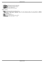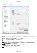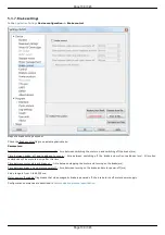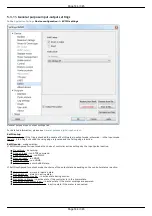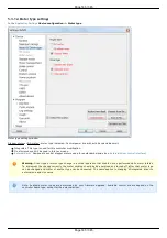
Reverse joystick - Reverse the joystick effects. Joystick deviation to large values results in negative speed and vice versa.
Button Joystick calibration opens calibration dialog box.
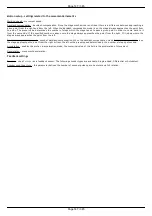
Dialog box of Joystick Calibration
Calibration is automatic border and the dead zone detection. Below is the process description:
Move the joystick to extremes to determine the borders. The range of all measured values is represented in a green line.
Release the joystick and press the Start to initiate detection of the dead zone. Within 5 seconds imitate accidental influences on the
joystick, which should not be recognized as deviation from the joystick zero position. The dead zone range is represented in red.
Pressing the Apply button will send the computed values into the Settings window. Pressing OK button will send the values and close
the calibration dialog box.
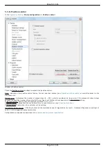
Left button and Right button blocks contain button settings.
Pushed Position - determines the state (pressed or released button) which is considered the motion signal by the controller.
Open - released button is considered to be a motion command.
Close - depressed button is considered to be a motion command.
Click settings block lets one to set up button "click" behaviour. A rapid press of a button is interpreted as a "click".
Max click time - Maximum click time. Until this amount of time is elapsed controller will not start moving with first speed (see below).
Delta - Relative position offset. Controller will do a shift on offset with each click.
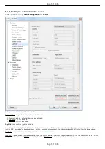
Speed settings block contains timeout and speed settings.
Timeout [i] - the time after which the speed switches from Speed[i] to Speed[i+1]. If any of the Timeout[i] is equal to zero, no
switching to the next speeds will occur.
Speed[i] - speed of the motor after time equal to Timeout[i-1]. If any of the speeds is equal to zero, no switching to this and
subsequent speeds will occur.
Configuration commands are described in
Communication protocol specification
.
Page 142 / 345
Page 142 / 345
Summary of Contents for 8SMC5-USB
Page 30: ...Linux Page 30 345 Page 30 345 ...
Page 83: ...Connection of magnetic brake to one axis or two axis systems Page 83 345 Page 83 345 ...
Page 87: ...Scheme of buttons connection to the HDB 26 connector Page 87 345 Page 87 345 ...
Page 99: ...Page 99 345 Page 99 345 ...
Page 167: ...Vertical load capacity the maximum vertical load on the stage Page 167 345 Page 167 345 ...
Page 186: ...Click Next Click Continue anyway Page 186 345 Page 186 345 ...
Page 188: ...Page 188 345 Page 188 345 ...
Page 190: ...Page 190 345 Page 190 345 ...
Page 193: ...Page 193 345 Page 193 345 ...
Page 201: ...Select the XILab application in the Programs block Start it Page 201 345 Page 201 345 ...
Page 274: ...7 Files 1 Configuration files 2 Software Page 274 345 Page 274 345 ...
Page 331: ...Motorized Iris Diaphragms 8MID98 Motorized Iris Diaphragm Page 331 345 Page 331 345 ...
Page 338: ...8 Related products 1 Ethernet adapter Page 338 345 Page 338 345 ...
Page 339: ...8 1 Control via Ethernet 1 Overview 2 Administration Page 339 345 Page 339 345 ...

