Description:
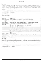
Read protection settings.
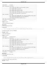
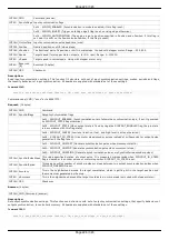
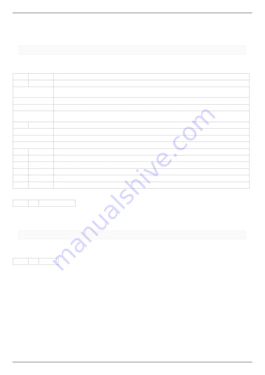
Command SEDS
result_t set_edges_settings (device_t id, const edges_settings_t* edges_settings)
Command code (CMD): "seds" or 0x73646573.
Request: (26 bytes)
INT32U CMD
Command
INT8U
BorderFlags
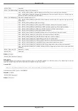
Border flags, specify types of borders and motor behaviour on borders.
0x01 - BORDER_IS_ENCODER (Borders are fixed by predetermined encoder values, if set; borders position on
limit switches, if not set.)
0x02 - BORDER_STOP_LEFT (Motor should stop on left border.)
0x04 - BORDER_STOP_RIGHT (Motor should stop on right border.)
0x08 - BORDERS_SWAP_MISSET_DETECTION (Motor should stop on both borders. Need to save motor then
wrong border settings is se)
INT8U
EnderFlags
Ender flags, specify electrical behaviour of limit switches like order and pulled positions.
0x01 - ENDER_SWAP (First limit switch on the right side, if set; otherwise on the left side.)
0x02 - ENDER_SW1_ACTIVE_LOW (1 - Limit switch connnected to pin SW1 is triggered by a low level on pin.)
0x04 - ENDER_SW2_ACTIVE_LOW (1 - Limit switch connnected to pin SW2 is triggered by a low level on pin.)
INT32S LeftBorder
Left border position, used if BORDER_IS_ENCODER flag is set.
INT16S uLeftBorder
Left border position in 1/256 microsteps(used with stepper motor only). Range: -255..255.
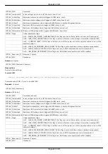
INT32S RightBorder
Right border position, used if BORDER_IS_ENCODER flag is set.
INT16S uRightBorder Right border position in 1/256 microsteps. Used with stepper motor only. Range: -255..255.
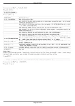
INT8U
Reserved [6] Reserved (6 bytes)
INT16U CRC
Checksum
Answer: (4 bytes)
INT32U CMD Command (answer)
Description:
Set border and limit switches settings.
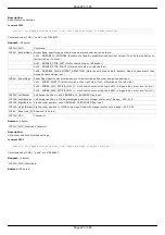
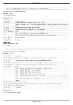
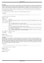
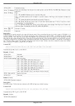
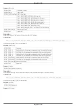
Command GEDS
result_t get_edges_settings (device_t id, edges_settings_t* edges_settings)
Command code (CMD): "geds" or 0x73646567.
Request: (4 bytes)
INT32U CMD Command
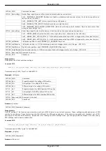
Answer: (26 bytes)
Page 223 / 345
Page 223 / 345
Summary of Contents for 8SMC5-USB
Page 30: ...Linux Page 30 345 Page 30 345 ...
Page 83: ...Connection of magnetic brake to one axis or two axis systems Page 83 345 Page 83 345 ...
Page 87: ...Scheme of buttons connection to the HDB 26 connector Page 87 345 Page 87 345 ...
Page 99: ...Page 99 345 Page 99 345 ...
Page 167: ...Vertical load capacity the maximum vertical load on the stage Page 167 345 Page 167 345 ...
Page 186: ...Click Next Click Continue anyway Page 186 345 Page 186 345 ...
Page 188: ...Page 188 345 Page 188 345 ...
Page 190: ...Page 190 345 Page 190 345 ...
Page 193: ...Page 193 345 Page 193 345 ...
Page 201: ...Select the XILab application in the Programs block Start it Page 201 345 Page 201 345 ...
Page 274: ...7 Files 1 Configuration files 2 Software Page 274 345 Page 274 345 ...
Page 331: ...Motorized Iris Diaphragms 8MID98 Motorized Iris Diaphragm Page 331 345 Page 331 345 ...
Page 338: ...8 Related products 1 Ethernet adapter Page 338 345 Page 338 345 ...
Page 339: ...8 1 Control via Ethernet 1 Overview 2 Administration Page 339 345 Page 339 345 ...

