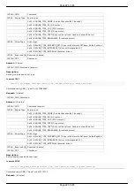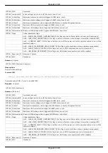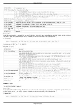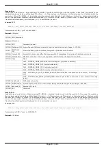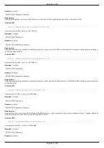
INT32U CMD
Command (answer)
INT8U
CTPMinError
Minimum contrast steps from step motor encoder position, wich set STATE_CTP_ERROR flag. Measured in steps
step motor.
INT8U
CTPFlags
Flags.
0x01 - CTP_ENABLED (Position control is enabled, if flag set.)
0x02 - CTP_BASE (Position control is based on revolution sensor, if this flag is set; otherwise it is based on
encoder.)
0x04 - CTP_ALARM_ON_ERROR (Set ALARM on mismatch, if flag set.)
0x08 - REV_SENS_INV (Sensor is active when it 0 and invert makes active level 1. That is, if you do not invert,
it is normal logic - 0 is the activation.)
0x10 - CTP_ERROR_CORRECTION (Correct errors which appear when slippage if the flag is set. It works only
with the encoder. Incompatible with flag CTP_ALARM_ON_ERROR.)
INT8U
Reserved
[10]
Reserved (10 bytes)
INT16U CRC
Checksum
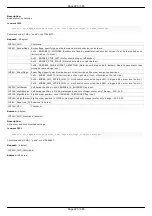
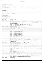
Description:
Read settings of control position(is only used with stepper motor). When controlling the step motor with encoder (CTP_BASE 0) it is
possible to detect the loss of steps. The controller knows the number of steps per revolution (GENG :: StepsPerRev) and the encoder
resolution (GFBS :: IPT). When the control (flag CTP_ENABLED), the controller stores the current position in the footsteps of SM and
the current position of the encoder. Further, at each step of the position encoder is converted into steps and if the difference is greater
CTPMinError, a flag STATE_CTP_ERROR. When controlling the step motor with speed sensor (CTP_BASE 1), the position is controlled by
him. The active edge of input clock controller stores the current value of steps. Further, at each turn checks how many steps shifted.
When a mismatch CTPMinError a flag STATE_CTP_ERROR.
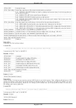
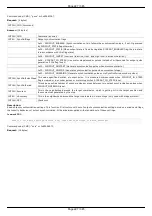
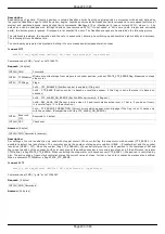
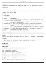
Command SURT
result_t set_uart_settings (device_t id, const uart_settings_t* uart_settings)
Command code (CMD): "surt" or 0x74727573.
Request: (16 bytes)
INT32U CMD
Command
INT32U Speed
UART speed
INT16U UARTSetupFlags UART setup flags
0x03 - UART_PARITY_BITS (Bits of the parity.)
0x00 - UART_PARITY_BIT_EVEN (Parity bit 1, if even)
0x01 - UART_PARITY_BIT_ODD (Parity bit 1, if odd)
0x02 - UART_PARITY_BIT_SPACE (Parity bit always 0)
0x03 - UART_PARITY_BIT_MARK (Parity bit always 1)
0x04 - UART_PARITY_BIT_USE (None parity)
0x08 - UART_STOP_BIT (If set - one stop bit, else two stop bit)
INT8U
Reserved [4]
Reserved (4 bytes)
INT16U CRC
Checksum
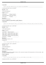
Answer: (4 bytes)
INT32U CMD Command (answer)
Description:
Set UART settings. This function send structure with UART settings to controller's memory.
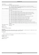
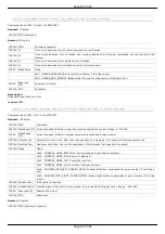
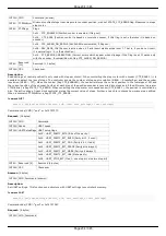
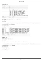
Command GURT
result_t get_uart_settings (device_t id, uart_settings_t* uart_settings)
Command code (CMD): "gurt" or 0x74727567.
Request: (4 bytes)
INT32U CMD Command
Page 234 / 345
Page 234 / 345
Summary of Contents for 8SMC5-USB
Page 30: ...Linux Page 30 345 Page 30 345 ...
Page 83: ...Connection of magnetic brake to one axis or two axis systems Page 83 345 Page 83 345 ...
Page 87: ...Scheme of buttons connection to the HDB 26 connector Page 87 345 Page 87 345 ...
Page 99: ...Page 99 345 Page 99 345 ...
Page 167: ...Vertical load capacity the maximum vertical load on the stage Page 167 345 Page 167 345 ...
Page 186: ...Click Next Click Continue anyway Page 186 345 Page 186 345 ...
Page 188: ...Page 188 345 Page 188 345 ...
Page 190: ...Page 190 345 Page 190 345 ...
Page 193: ...Page 193 345 Page 193 345 ...
Page 201: ...Select the XILab application in the Programs block Start it Page 201 345 Page 201 345 ...
Page 274: ...7 Files 1 Configuration files 2 Software Page 274 345 Page 274 345 ...
Page 331: ...Motorized Iris Diaphragms 8MID98 Motorized Iris Diaphragm Page 331 345 Page 331 345 ...
Page 338: ...8 Related products 1 Ethernet adapter Page 338 345 Page 338 345 ...
Page 339: ...8 1 Control via Ethernet 1 Overview 2 Administration Page 339 345 Page 339 345 ...

