4.2.8. PID-algorithm for DC engine control
Algorithm description
DC engine is controlled by the PID regulator, with the coordinate as the controlled parameter. The controlled coordinate changes
according to motion settings and incoming commands to provide motion capability. We will call controller coordinate the running
position. DC engine winding PWM signal fill factor is the control signal of the regulator.
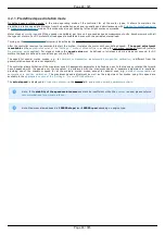
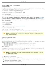
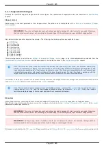
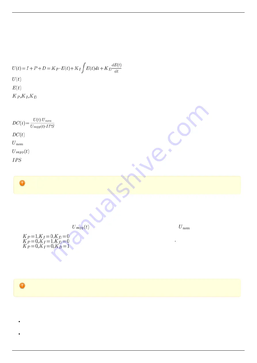
The control action is calculated according to the following formula:
, where:
- is the control action
- is difference between the running coordinate and the current motor coordinate
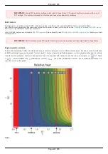
The resulting value is normalized according to the following formula to make PID regulator action independent of motor type, feedback
sensor and working voltage:
, where:
- is the PWM fill factor
- is the nominal (maximum) motor voltage, (see
).
- is the current supply voltage
- is the feedback encoder resolution in counts per revolution
This approach allows to change motor type, feedback sensor and voltage supply unit without reconfiguring PID regulator.
Warning. Do not forget to change
accoring to abovementioned formula if you are going to
change maximum motor voltage.
Particular properties of the algorithm
PID regulator coefficients
are normalized to keep optimal PID regulator coefficients in [0..65535] range.
Let's consider the effects different components have for better understanding.
We will assume the supply voltage
is constant and equal to the motor nominal voltage
. With this assumption PWM fill
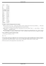
factor will be equal to 1 in the following cases:
1.
- if target position is ahead of real position by 256 motor shaft revolutions
2.
- if integral in the formula above is equal to 52.5 revolutions second
3.
- if real motor speed is higher than the required speed by 96000 rpm.
Reaching target position
Target position is considered to be reached when motor shaft reaches the target position. Some oscillations around target position are
possible. Motor will need some time to stop and return to correct position if smooth deceleration is not used and an immediate stop
command is received or an emergency stop by limit switch has happened.
Warning. Long time oscillations around the target position while the motion is considered finished are possible if the
PID regulator is set up incorrectly.
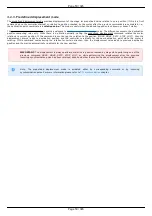
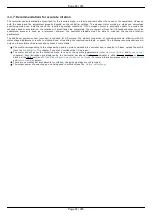
PID regulator tuning recommendations
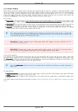
There are three quality criterions used when tuning PID regulator:
Speed maintenance accuracy, defined as a mean deviation of current speed from desired speed. Speed maintenance is
considered to work optimally if the speed takes no more than three distinct values when moving. It is impossible to achieve
greater accuracy because speed values are quantized.
Position reach quality, defined by the following criterions:
Page 55 / 345
Page 55 / 345
Summary of Contents for 8SMC5-USB
Page 30: ...Linux Page 30 345 Page 30 345 ...
Page 83: ...Connection of magnetic brake to one axis or two axis systems Page 83 345 Page 83 345 ...
Page 87: ...Scheme of buttons connection to the HDB 26 connector Page 87 345 Page 87 345 ...
Page 99: ...Page 99 345 Page 99 345 ...
Page 167: ...Vertical load capacity the maximum vertical load on the stage Page 167 345 Page 167 345 ...
Page 186: ...Click Next Click Continue anyway Page 186 345 Page 186 345 ...
Page 188: ...Page 188 345 Page 188 345 ...
Page 190: ...Page 190 345 Page 190 345 ...
Page 193: ...Page 193 345 Page 193 345 ...
Page 201: ...Select the XILab application in the Programs block Start it Page 201 345 Page 201 345 ...
Page 274: ...7 Files 1 Configuration files 2 Software Page 274 345 Page 274 345 ...
Page 331: ...Motorized Iris Diaphragms 8MID98 Motorized Iris Diaphragm Page 331 345 Page 331 345 ...
Page 338: ...8 Related products 1 Ethernet adapter Page 338 345 Page 338 345 ...
Page 339: ...8 1 Control via Ethernet 1 Overview 2 Administration Page 339 345 Page 339 345 ...

