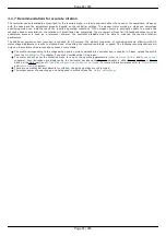
4.3.4. Automatic Home position calibration
This feature is used for detection and placing the movement to the starting position. This option of the controller is designed for simple
search of "Home", or "Zero" position by user himself, with no need of any programming skills. The Home position is set relative to one
or two external sensors and/or to an external signal.
Automatic Home position calibration feature is configured by user in Device configuration->Home position folder of XILab software (see
the
chapter) and is activated by the button in
.
After this feature is activated, the controller rotates the motor to the defined direction with normal speed to quickly locate the stop
position. After finding the boundary position controller assigns motor back half a turn and begins rotate the motor to the defined
direction, but with another calibration speed. The calibration speed is usually set lower than the normal rotation speed in order to
improve the calibration accuracy. There are three ways to determine the completion of the motion, according to user-defined
preferences:
is reached, the actual configuration of limit switches is used (e.g., polarity, location). For more
Motion range and limit switches
chapter.
rotation until a signal from the
is received, the actual configuration of synchronization input is
used. For more details please refer to
chapter. If the synchronization input is switched off by program,
the signal from it will never be processed.
rotation until a signal from the
is received, the actual configuration of revolution sensor is used. For
chapter.
Successful completion of home position calibration results in assertion of the STATE_IS_HOMED flag in the
. If
after this position somehow got lost (stop on
while moving,
, turns the
),
the corresponding flag is dropped and it is necessary to re-calibrate the home position.
Note. If command
or command
are executed while the engine is stopped then it
isn't necessary to re-calibrate the home position and the STATE_IS_HOMED flag is not dropped.
Note. If the completion of the motion should happen at the limit switch, the calibration program is not crashed.
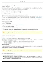
Fine calibration
After the first displacement the controller position is defined. However, some additional rotation may probably get turned on before the
movement to Home position is performed. It provides fine Home position calibration that may reach 1/256 of the step for stages with
stepper motors or 1 encoder count for stages with DC motors. If the corresponding flag is switched on, the controller rotates the motor
to user-defined direction with defined rotation speed until a signal either from the
or from the
is reached, according to user-defined preferences. Using the signal from the sensor on the shaft
from motor to reducer and performing the motion with the small speed does make sense. It provides the maximum accuracy. Since
first and second movement signals might happen simultaneously a flag is provided, which will start tracking second motion end signal
only after motor shaft half-turn. This allows avoiding the signals of the completion of the first and second motions to be in ambiguous
sequence. As a result of optional second motion, the calibrating position becomes more accurate.
Note. If the second phase of the motion is used, the first motion usually can be performed at the high speed since it
provides just a coarse calibration and the accuracy is not required there. The accuracy will not improve if the second
limit switch is used for the second phase of the motion since its physical characteristics are the same as for the first
limit switch.
Finally the controller moves the motor to the defined direction with the defined speed at the defined Standoff distance. This is what
required to reach the Home position.
Note. The position reached as a result of calibration will slightly depend on the speed of the last motion until the
selected sensor responsed. Therefore, don't change the speed parameters for further successful reaching the same
position.
The automatic Home position calibration features are described in the
chapter.
The parameters configuration commands are described in the
Communication protocol specification
chapter
The position calibration command is described in the
Communication protocol specification
chapter.
A set_zero
is supplied with XiLab software pack, providing the automatic Home position configuration. This script changes the
Standoff setting in Home position folder, making the actual position as the Home one.
Page 67 / 345
Page 67 / 345
Summary of Contents for 8SMC5-USB
Page 30: ...Linux Page 30 345 Page 30 345 ...
Page 83: ...Connection of magnetic brake to one axis or two axis systems Page 83 345 Page 83 345 ...
Page 87: ...Scheme of buttons connection to the HDB 26 connector Page 87 345 Page 87 345 ...
Page 99: ...Page 99 345 Page 99 345 ...
Page 167: ...Vertical load capacity the maximum vertical load on the stage Page 167 345 Page 167 345 ...
Page 186: ...Click Next Click Continue anyway Page 186 345 Page 186 345 ...
Page 188: ...Page 188 345 Page 188 345 ...
Page 190: ...Page 190 345 Page 190 345 ...
Page 193: ...Page 193 345 Page 193 345 ...
Page 201: ...Select the XILab application in the Programs block Start it Page 201 345 Page 201 345 ...
Page 274: ...7 Files 1 Configuration files 2 Software Page 274 345 Page 274 345 ...
Page 331: ...Motorized Iris Diaphragms 8MID98 Motorized Iris Diaphragm Page 331 345 Page 331 345 ...
Page 338: ...8 Related products 1 Ethernet adapter Page 338 345 Page 338 345 ...
Page 339: ...8 1 Control via Ethernet 1 Overview 2 Administration Page 339 345 Page 339 345 ...


