4.3.5. Operation with encoders
Application of encoders
Encoders are designed for creation of accurate and fast feedback according to the coordinate for all the electric motor types.The
feedback is performed by the motor shaft position, by stage's linear position, by the motorized table rotation angle or by any other
parameter related to the shaft position and measured by using the two-channel quadrature encoder complying the requirements
described in
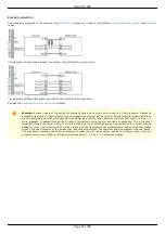
chapter for the appropriate controller type. Controller 8SMC5 supports differential encoders and
simple (single-ended) encoders.
What is quadrature encoder?
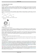
Encoder is a mechanical motion sensor. The quadrature encoder is designed for direct detection of the shaft position. The sensor
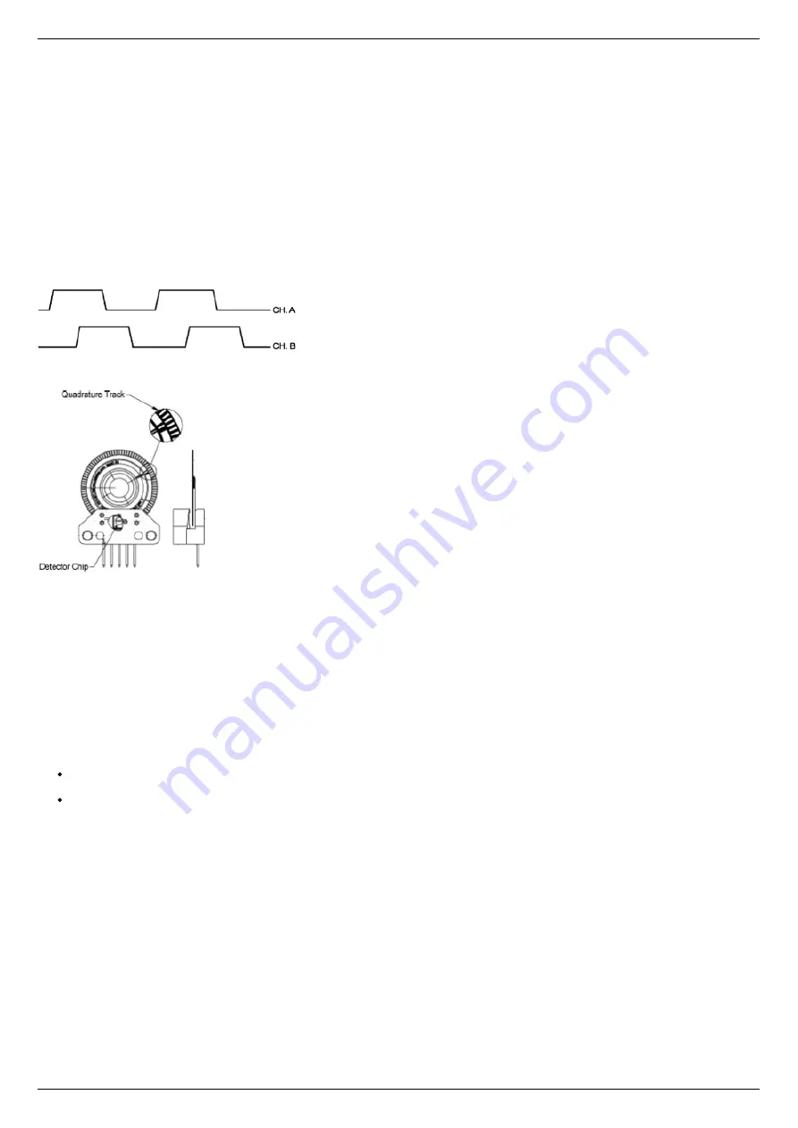
transmits the relative shaft position by using two electric signals at СН А and СН В channels shifted relative to each other at 1/4 of
period.
The signals at СН А and СН В outputs of quadrature encoder.
An optical quadrature encoder mechanics.
An optical quadrature encoder mechanics is shown at the figure above. There are two optocouplers used. The operational principle of
an optocoupler is as following: a LED and a detector are arranged opposite to each other from different sides of a disc. The optocoupler
opens when disc's "window" coincides with the detector (the outgoing signal is logic zero). The outgoing signal is logic one if the
detector is closed by opaque part of the disc.
Number of steps per revolution (CPR) is the main parameter of the quadrature encoder. The standard resolution values for encoder are
from 24 to 1024 CPR. Each period of signal alteration is interpreted by 1, 2 or 4 codes which is corresponding to X1, X2 and X4
operating modes. This controller uses the most accurate X4 mode. The maximum frequency of each encoder's signal depends on the
applied encoder itself, since for 200 kHz in X4 mode the controller can read up to 800,000 encoder counts per second.
Controller's features
There are two operating modes with encoder available for the controller:
the encoder is used as the main position sensor (this is the main operating mode for DC motors and the optional one for stepper
motors).
slippage, backlash or steps loss detection (the recommended mode for joint operations with stepper motors, in case the encoder
is not used as a primary position sensor, see
).
Driving encoder mode
This is the mode when all parameters of the engine including position and velocity are measured directly by the encoder and are
denominated basing on counts of encoder. The position is displayed directly in the encoder counts, the speed is denominated in RPM
(revolutions per minute). The speed is calculated by the controller basing on the speed alteration data as well as on the number of
encoder pulses per one complete revolution of the motor shaft that are displayed in feedback configuration block at the Settings of
kinematics (
) folder. Note that in the case of DC motor the
movement to the predefined point
as well as all their derivations use PID control algorithms and the
The driving encoder mode optimizes stepper motor control, this leads to noise reducing and facilitates a stable passage of the resonant
speeds with no risk of steps loss when the coordinate flounders and the recurrent
is required.
New!
New motor control algorithm is included in the latest firmware. The algorithm add encoder close-loop feedback suppressing
motor oscillations and acoustic noises. It makes almost all motors several times faster without any step loss. It all comes with a free
update of firmware and software. The new algorithm is available with firmware 4.0.7+ which can we downloaded from our
page or updated through XiLab. Use XiLab 1.13.13+ and set Feedback to Encoder on the Device configuration ->
.
Note, that position is in encoder counts now.
Page 69 / 345
Page 69 / 345
Summary of Contents for 8SMC5-USB
Page 30: ...Linux Page 30 345 Page 30 345 ...
Page 83: ...Connection of magnetic brake to one axis or two axis systems Page 83 345 Page 83 345 ...
Page 87: ...Scheme of buttons connection to the HDB 26 connector Page 87 345 Page 87 345 ...
Page 99: ...Page 99 345 Page 99 345 ...
Page 167: ...Vertical load capacity the maximum vertical load on the stage Page 167 345 Page 167 345 ...
Page 186: ...Click Next Click Continue anyway Page 186 345 Page 186 345 ...
Page 188: ...Page 188 345 Page 188 345 ...
Page 190: ...Page 190 345 Page 190 345 ...
Page 193: ...Page 193 345 Page 193 345 ...
Page 201: ...Select the XILab application in the Programs block Start it Page 201 345 Page 201 345 ...
Page 274: ...7 Files 1 Configuration files 2 Software Page 274 345 Page 274 345 ...
Page 331: ...Motorized Iris Diaphragms 8MID98 Motorized Iris Diaphragm Page 331 345 Page 331 345 ...
Page 338: ...8 Related products 1 Ethernet adapter Page 338 345 Page 338 345 ...
Page 339: ...8 1 Control via Ethernet 1 Overview 2 Administration Page 339 345 Page 339 345 ...

