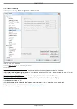
5.3.5. Home position settings
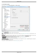
Device configuration -> Home position
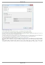
Home position settings window
by a specified offset. It is helpful when the current location of the stage is unknown but we know the base point position relative to
limit switch or some other signal, which is called home position.
Homing comes to the motor movement towards the predetermined 1st move direction (left or right) at Working speed until the signal
from the source stop after don't happen. Then the motor movement towards the opposite direction with the same speed until the
signal from the source stop after in the active state and continue half turn in the same direction. Then begins the precise movement in
a given direction 1st move direction at 1st move speed. The speed is usually set low enough to keep the next signal. Motor stops,
depending on the stop after value, upon getting a sync input signal, signal from RPM sensor or reaching of the limit switch.
If the flag Use second phase of homing is checked the homing algorithm rotates the motor in a predetermined 2nd move direction (left
or right) with the 2nd move speed.
If the flag Blind half turn is checked the motor ignores the end of the second phase signal during half a turn. It helps to set an
unambiguous detection order for the sensors that have the first and the second movement phases signals close each other.
The third phase of homing is the absolute offset to the distance standoff.
The resulting point is called a home position. It is important that its location on the stage does not depend on the calibration starting
point.
Use fast homing algorithm option uses Working speed (see
Settings of kinematics (stepper motor)
page) for the first phase of homing
to speed up the process.
Configuration commands are described in the
Communication protocol specification
section.
Page 137 / 345
Page 137 / 345
Summary of Contents for 8SMC5-USB
Page 30: ...Linux Page 30 345 Page 30 345 ...
Page 83: ...Connection of magnetic brake to one axis or two axis systems Page 83 345 Page 83 345 ...
Page 87: ...Scheme of buttons connection to the HDB 26 connector Page 87 345 Page 87 345 ...
Page 99: ...Page 99 345 Page 99 345 ...
Page 167: ...Vertical load capacity the maximum vertical load on the stage Page 167 345 Page 167 345 ...
Page 186: ...Click Next Click Continue anyway Page 186 345 Page 186 345 ...
Page 188: ...Page 188 345 Page 188 345 ...
Page 190: ...Page 190 345 Page 190 345 ...
Page 193: ...Page 193 345 Page 193 345 ...
Page 201: ...Select the XILab application in the Programs block Start it Page 201 345 Page 201 345 ...
Page 274: ...7 Files 1 Configuration files 2 Software Page 274 345 Page 274 345 ...
Page 331: ...Motorized Iris Diaphragms 8MID98 Motorized Iris Diaphragm Page 331 345 Page 331 345 ...
Page 338: ...8 Related products 1 Ethernet adapter Page 338 345 Page 338 345 ...
Page 339: ...8 1 Control via Ethernet 1 Overview 2 Administration Page 339 345 Page 339 345 ...


