background image

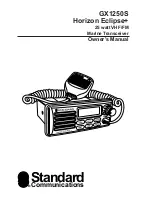
GX1250S

Horizon

25 watt VHF/FM

Marine Transceiver

Owner’s Manual

Standard

Communications

Summary of Contents for Horizon Eclipse+ GX1250S

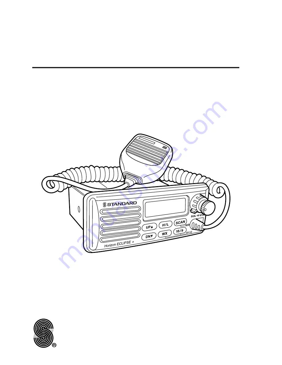
Page 1: ...GX1250S Horizon Eclipse 25 watt VHF FM Marine Transceiver Owner s Manual Standard Communications ...

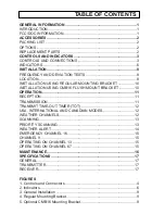
Page 2: ... USING CMB16 FLUSH MOUNT BRACKET 10 OPERATION 11 RECEPTION 11 TRANSMISSION 11 TRANSMIT TIME OUT TIMER TOT 12 USA INTERNATIONAL AND CANADIAN MODES 12 WEATHER CHANNELS 12 SCANNING 13 PRIORITY SCANNING 13 WEATHER ALERT 14 EMERGENCY CHANNEL 16 15 CHANNEL 9 15 OPERATING ON CHANNEL 13 15 OPERATING ON CHANNEL 67 15 MAINTENANCE 16 SPECIFICATIONS 17 GENERAL 17 TRANSMITTER 17 RECEIVER 17 FIGURES 1 Controls ...

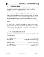
Page 3: ... the red 16 9 key Weather channels can be also be accessed immediately by pressing the WX key The power output is 25 watts in high range and 1 watt in the low range These ranges are manually selected by the front panel H L key except on channels where low range power is mandatory On these channels low range is automatically selected 1 2 FCC DOC INFORMATION The following data pertaining to the tran...

Page 4: ...k it for the following contents GX1250S Eclipse Transceiver CMP348W Microphone Attached to the transceiver Mounting Bracket and attaching hardware Power Cable Owner s Manual Owner s Manual Supplement Hanger Kit for Microphone 2 2 OPTIONS CMB16 Flush Mount Bracket 201S Remote Extension Speaker with RCA Phono Plug 201SZ Flush mount Speaker 101 Extension Speaker 2 3 REPLACEMENT PARTS Microphone Assem...

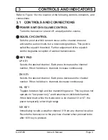
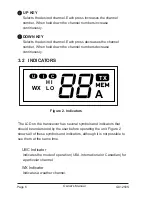
Page 5: ...ions e e KEY PAD UP KEY Selects the desired channel Each press increases the channel number When held down channels increase continuously DN KEY Selects the desired channel Each press decreases the channel number When held down channels decrease continuously H L KEY Toggles between high and low transmitting power This key does not operate on low power only and transmission inhibited channels When ...

Page 6: ...ual GX1250S Page 4 Horizon ECLIPSE UP H L SCAN DN WX 16 9 R D SQL VOL U I C DN UP q q w w e e r r t t y y u u i i o o 00 Figure 1 Controls and Connectors 11 FRONT PANEL REAR PANEL MICROPHONE FRONT VIEW TOP VIEW 22 ...

Page 7: ...is reset and scan channels are erased r r SPEAKER t t LIQUID CRYSTAL DISPLAY LCD See Section 3 2 for Indicators y y ANTENNA JACK Connects the antenna to the transceiver Use a marine VHF antenna with an impedance of 50 ohms u u DC INPUT CABLE Connects the transceiver to a DC power supply of 13 8 V i i EXTERNAL SPEAKER JACK Connects an optional external speaker to the transceiver Use a speaker with ...

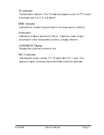
Page 8: ...usly 3 2 INDICATORS The LCD on the transceiver has several symbols and indicators that should be understood by the user before operating the unit Figure 2 shows all of these symbols and indicators although it is not possible to see them at the same time U I C Indicator Indicates the mode of operation USA International or Canadian for a particular channel WX Indicator Indicates a weather channel Ow...

Page 9: ...e transceiver s memory A Indicator Indicates a simplex channel in USA or Canadian mode whose counterpart in the International mode is a duplex channel 7 SEGMENT Display Displays the channel number in use HI LO Indicator Indicates the power setting HI 25 watts and LO 1 watt This display is blank if a transmission inhibited channel is selected Owner s Manual GX1250S Page 7 ...

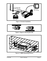
Page 10: ...has nearby space for installation of a microphone hanger 2 Install the unit in accordance with paragraph 4 3 or 4 4 In each appears an instruction to connect the power supply and antenna Where that appears the following three steps should be performed a At the rear of the transceiver connect the antenna cable to the antenna jack The antenna must have a PL259 connector RG8 or RG213 coaxial cable mu...

Page 11: ...Owner s Manual GX1250S Page 9 Figure 3 General Installation Figure 4 Regular Mounting Bracket Figure 5 CMB16 Mounting Bracket SPEAKER OPTIONAL BATTERY WATERPROOF DECK OUTLET ...

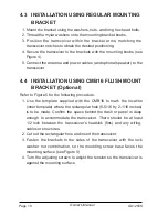
Page 12: ...BRACKET Optional Refer to Figure 5 for the following procedure 1 Use the template supplied with the CMB16 to mark the location inner template where the rectangular hole 5 5 16 by 2 1 16 inches is to be made Confirm the space behind the dash or panel is deep enough to accommodate the transceiver There should be at least 1 2 inch between the transceiver s heatsink fins and any wiring cables or struc...

Page 13: ...op immediately after the noise disappears This condition is known as the Squelch Threshold If the SQUELCH CONTROL knob is turned clockwise past this point weak signals are not received No noise and no signals are heard until a signal is received that exceeds the squelch threshold 7 To change channels press the UP or DN key Sometimes a slight adjustment of the squelch threshold needs to be made bec...

Page 14: ...witches to the receiving mode even if the PTT switch is still held down Before transmitting again the PTT switch must first be released and be pressed again 5 4 USA INTERNATIONAL AND CANADIAN MODES 1 To change the modes hold down the 16 9 key and press the WX key The mode changes from USA to International to Canadian with each press of the WX key 2 U is displayed for the USA mode I is displayed fo...

Page 15: ... MEM is deleted 5 7 PRIORITY SCANNING Emergency channel 16 can be set as the priority channel for scanning by performing the following 1 Turn off the transceiver power 2 Press and hold the SCAN key and turn the power back on A p will be shown to the left of 16 on the display to indicate that priority scan is enabled NOTE To scan or priority scan 2 or more channels must be memorized in scan memory ...

Page 16: ... weather reports on the weather channels The transceiver is capable of receiving this alert if the following steps are performed 1 Program weather channels into the transceiver s memory for scanning Follow the same procedure as used for regular channels in Section 5 6 2 Press the SCAN key to start a scan 3 The programmed weather channels are scanned along with the regular programmed channels Howev...

Page 17: ...lect channel 9 5 11 OPERATING ON CHANNEL 13 Channel 13 is used at docks bridges and for maneuvering in port Messages on this channel must concern navigation only such as meeting and passing in restricted waters Messages must be short and low power used In emergencies and when approaching blind river bends high power is allowed Hold down the H L key to temporarily switch to high power Hi power can ...

Page 18: ...e DC power cables away from engine Add noise suppressor to the power cable Change to resistive spark plug wires and or add an alternator whine filter The external speaker jack accepts only RCA phono plugs Normal transceiver operation causes internal speaker cut off when external speaker is plugged in The transceiver may be tuned to a duplex channel meant for ship to shore radiotelephone communicat...

Page 19: ...t 25 W Hi 1W Lo Conducted Spurious Emissions 65 dB Hi 50 dB Lo FM Hum and Noise 40 dB min Audio Response within 2 8 of 6 dB octave pre emphasis Audio Distortion 5 Modulation 16F3 Frequency Stability 20 to 50 C 0 0005 7 3 RECEIVER Sensitivity 20 dB Quieting 0 4 µV 12 dB SINAD 0 35 µV Squelch Sensitivity Threshold 0 2 µV Bandwidth Acceptable Radio Frequency Displacement 4 5 kHz Selectivity Spurious ...

Page 20: ...tandard Communications Standard Communication Corp P O Box 92151 Los Angeles CA 90009 2151 Telephone 310 532 5300 STANDARD COMMUNICATIONS CORP 1998 All Rights Reserved Printed in Japan 03 1999 175B851012 ...

Reviews: