Page 18
CP590
BLACK
RED
GREEN
BLUE
BROWN
GRAY
WHITE
YELLOW
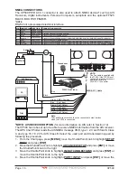
PIN WIRE COLOR FUNCTION
No Connection
No Connection
NMEA Common
Port4 Input
Port4 Output
Port5 Input
Port5 Output
No Connection
1
2
3
4
5
6
7
8
*
*
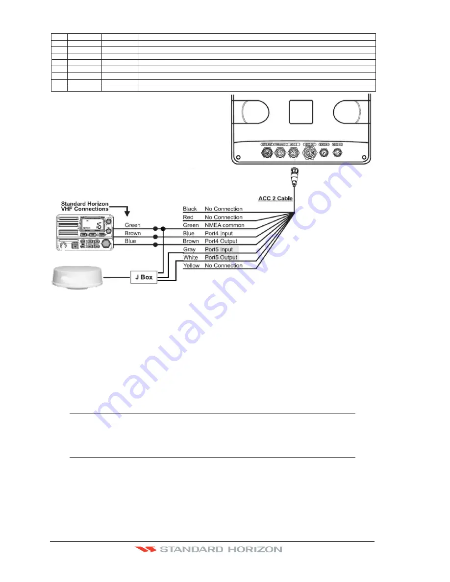
CONNECTION EXAMPLE
Common (ground) for NMEA devices**
Connect to Output of NMEA device
Connect to Input of NMEA device
. Default is NMEA-0183 with GLL, RMB, RMC and XTE sentences
Connect to Output of NMEA device
Connect to Input of NMEA device
. Default is NMEA-0183 with GLL, RMB, RMC and XTE sentences
**
**
**
**
*
NOTE: RADAR Antenna connection
(optional)
For Radar Installation instructions visit www.standardhorizon.com and click on Owner’s
Manuals and click to down load files called Radar Installation Manual and Radar Operation
Manual.
**NOTE
RS232 not opto-isolated electrical interface.
VHF Connections
To connect the CP590 to a VHF, a port will be needed to be selected. Refer to the ACC 2
connections for a connection example.
NOTE
The optional FF525 uses port 2 when connected and the optional Radar antenna uses port 5. When
these optional devices are connected use port 1, 2 or 4 Input and Output to connect to the VHF radio.
Some manufacturers of DSC VHF’s are not capable of receiving NMEA DSC sentences from the
CP590. Refer to the Owner’s Manual and confirm the VHF can receive NMEA DSC and DSE
sentences.
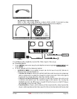
VGA Video Output
The CP590 has:
·
One VGA output
Allows connection to a compatible TV or monitor using the optional VGAC10
adapter cable.
Summary of Contents for CP590
Page 1: ......
Page 2: ...CP590 12 WAAS GPS Chart Plotter Owner s Manual GPS Chart Plotters ...
Page 5: ...Page 6 CP590 ...
Page 33: ...Page 34 CP590 ...
Page 43: ...Page 44 CP590 ...
Page 47: ...Page 48 CP590 ...
Page 57: ...Page 58 CP590 ...
Page 73: ...Page 74 CP590 ...
Page 77: ...Page 78 CP590 ...
Page 103: ...Page 104 CP590 ...
Page 117: ...Page 118 CP590 ...
Page 123: ...Page 124 CP590 ...
Page 127: ...Page 128 CP590 ...
Page 134: ......

