background image

Page 10                                                          Owner’s Manual                                                           MST70

GENERAL FUNCTIONS
Power ON/OFF

To turn the unit ON, press the 

POWER

 button. The unit will resume the mode 

that was selected when it was last turned off.
To turn the unit off, press the 

POWER

 button again. Note that when the unit is 

turned OFF, the clock is displayed.

Controls

The Volume, Bass, Treble, Balance and Fader controls are selected electronically. 

The default selection is the Volume control. To select another control, press the 

SEL

  button  repeatedly  until  the  name  of  the  control  you  require  is  displayed 

on the LCD. Each press cycles to the next control in sequence and the display  

shows the current setting for that control. If no button is pressed for 3 seconds, 

the  display  returns  to  normal  and  the  control  defaults  back  to  the  Volume 

control.

•    Volume:

  To  adjust  the  Volume,  simply  press  the 

VOL


  or 

VOL


buttons.  'VOL'  will  appear  on  the  display  along  with  a  number  indicating 

the  current  setting.  Press 

VOL 


to  increase  the  volume  level  or

  VOL 


to  decrease  the  volume  level.  A  level  of  63  on  the  display  indicates 

maximum volume.

•    Bass:

 Press the 

SEL

 button repeatedly until ‘BAS’ is displayed. Press 

VOL


to  increase  the  Bass  level  or 

VOL


to  decrease  the  Bass  level.  A  

level of 0 on the display indicates a flat Bass response.

•    Treble:

 Press the 

SEL

 button repeatedly until ‘TRE’ is displayed. Press 

VOL   


 to increase the Treble or 

VOL


 to decrease the Treble. A level of 0 on 

the display indicates a flat Treble response.

•    Balance:

 Press the 

SEL

 button repeatedly until ‘BL’ is displayed. Press  

VOL


to increase the volume in the right speakers. 'BL R'


is displayed along 

with  a  number  representing  the  volume  level  of  that  channel.  Press 

VOL


to increase the volume in the left speakers ('BL L' is displayed).

      To set the Balance to the center position, press 

VOL


 or  

VOL


 to 

reduce  the  front  or  rear  setting  until  ‘BL  C0’


is  displayed,  indicating  the 

centre position.

•    Fader:

 Press the 

SEL

 button repeatedly until ‘FA’ is displayed. 

      Press  

VOL 

 to fade the sound toward the Front speakers (and reduce 

the volume in the Rear speakers). ‘FA F’ is displayed along with a number 

to show the level of the Rear speaker setting.

      Press   

VOL


  to  fade  the  sound  to  the  Rear  speakers  (and  reduce  the 

volume in the front speakers). ‘FA R’ is displayed along with a number to 

show the level of the Rear speaker setting.

      To set the fader to the centre position, press 

VOL


 or 

VOL


 to reduce 

OPERATION

Summary of Contents for MST70

Page 1: ...MST70 Marine AM FM Cassette Stereo System With NOAA Weather Owner s Manual Marine Division of Yaesu U S A ...

Page 2: ... AND FITTING THE FRONT PANEL 3 INSTALLATION 4 Mounting 4 Upright or Overhead Mounting 4 Flush Mounting 5 Electrical Wiring 7 Speaker Connections 8 Antenna Connections 9 Fuse Replacement 9 CONTROLS 9 OPERATION 10 General Functions 10 Radio 11 Reset 13 Cassette Player 14 SPECIFICATIONS 15 ACCESSORIES 16 LIMITED WARRANTY 17 ...

Page 3: ...on when seeking or scanning Backlighting Special night vision orange back lighting of the display and all controls Built in Clock Automatically displays the time when the unit is switched off and at the press of a button when using the radio or cassette player FM Stereo Mono Switch Lets you manually disable stereo operation for improved FM reception in weak signal areas RCA Outputs Provides a sepa...

Page 4: ...lly FM signals can reflect from solid objects such as buildings or hills If these reflected signals are received along with signals arriving directly from the transmitter they may mix together to produce what is known as multipath distortion This distortion is heard as noise Often moving as little as 3 feet from your position will correct this problem FM signals travel in straight lines Because th...

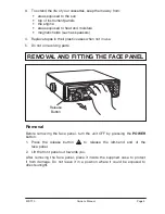
Page 5: ...ving the face panel place it inside the supplied case to protect it from damage Do not leave it in a position where it could be exposed to direct sunlight MST70 Owner s Manual Page 3 3 To extend the life of your cassettes keep them away from areas exposed to the sun top of instrument panels the engine areas exposed to heat and moisture magnetic fields such as speakers 4 Replace tapes in their plas...

Page 6: ...where it will not be subjected to spray or rain The diagrams below show the various methods of bracket mounting available Overhead Mount Upright or Overhead Mounting 1 Attach the two gimbal knobs and self adhesive rubber washers to the MST70 and slide the unit into the mounting bracket Ensure the rubber washers are between the bracket and the radio Tighten the knobs firmly 2 Temporarily position t...

Page 7: ...e selected has a suitable support shelf and the area is fully accessible you can use the supplied escutcheon panel as described later If the space behind the bulkhead or panel is largely inaccessible or there is no additional support shelf we recommend you use the optional CMB60 flush mounting kit available as an accessory This kit is more robust is fully self supporting and allows the MST70 to be...

Page 8: ... each locating pin and press the escutcheon into place Temporarily hold with tape if necessary 6 With the escutcheon firmly glued in place slide the MST70 through the slot from the front and push it all the way in while leaving a clearance for the front cover to hang in the open position Open the cover if necessary to ensure the correct clearance 7 Holding everything in position mark the location ...

Page 9: ... breaker This lead turns the radio ON and OFF Alternatively this wire can be connected directly to the battery s positive terminal and the MST70 switched ON and OFF using it s own controls 3 Connect the Black lead labelled GROUND to the battery s negative terminal or to the common negative bus in the electrical system Important Your MST70 is able to maintain it s memories when it is switched off b...

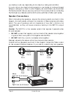
Page 10: ...of speakers with an impedance of less that 4 Ohms is not recommended as they will cause excessive loading of the MST70 s output circuit Caution The MST70 is a four speaker system that requires 2 separate wires for each speaker DO NOT connect the negative ve terminals of the speaker wires together or ground them to any part of the negative electrical Bus DO NOT short the ve and ve speaker wires tog...

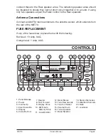
Page 11: ...f any of the fuses blow replace them with the following Red lead 10 Amp 3AG Orange lead 1 Amp 3AG CONTROLS SEL POWER LOC M S LOU MUT 100 WATTS W B AMS DSP REL MAN SEK VOL VOL MAN SEK 1 2 3 4 5 6 BND CONTROL 18 1 2 3 4 5 6 7 8 9 11 10 12 13 14 15 16 17 19 20 21 7 Rewind 8 Fast Forward 9 Display Clock 10 AMS Auto Memory Store 11 Local Distant 1 Panel Release 2 Power 3 Volume Up 4 Eject Cassette 5 Di...

Page 12: ...ton repeatedly until BAS is displayed Press VOL to increase the Bass level or VOL to decrease the Bass level A level of 0 on the display indicates a flat Bass response Treble Press the SEL button repeatedly until TRE is displayed Press VOL to increase the Treble or VOL to decrease the Treble A level of 0 on the display indicates a flat Treble response Balance Press the SEL button repeatedly until ...

Page 13: ...ctable frequency bands labelled FM1 FM2 FM3 MW1 and MW2 Bands FM1 FM3 are identical and cover the FM band from 87 5 MHz to 107 9 MHz The MW bands cover the AM frequencies from 530 kHz to 1710 kHz Up to 6 channels in each band can be stored in memory making 18 FM and 12 AM channels available The 3 FM and 2 AM bands allow stations from different areas to be stored and kept seperate e g Hometown FM s...

Page 14: ...ng to that frequency when finished The memories for that band will then contain the six strongest FM stations in your area In the AM mode the radio will begin tuning upwards from the currently selected frequency and will store the first six stations found Tuning will then stop Note If the AM stations you wish to store were not included because the memories were filled up by other unwanted stations...

Page 15: ...ck 1 Press the DSP button to display the clock 2 Now press and hold the DPS button while pressing the button to adjust the hours or the button to adjust the minutes RESET Your MST70 s functions are controlled by a microprocessor If after installation you find that some of the functions do not appear to work correctly you can reset the microprocessor to restore the radio to its default settings Not...

Page 16: ...the fastforward or rewind buttons Press for fastforward and for rewind regardless of which direction the tape is playing To stop fastforward or rewind press the opposite button i e press to cancel etc When the tape reaches the end the unit will automatically reverse the play direction and play the other side of the tape To change the play direction manually press and simultaneously The direction i...

Page 17: ...AM Radio Frequency Range 530 1710 kHz Intermediate Frequency 450 kHz Sensitivity 30 dB S N 20 dBµV Selectivity 9 kHz 30 dB Station Memories 12 MW1 MW2 Audio Amplifier Audio Output 10 Dist 60 Watts Total 15 Watts RMS x 4CH Output Impedance 4 ohms channel Bass Control 8 dB 100 Hz Treble Control 8 dB 10 kHz Stereo Cassette Deck Deck type 4 track 2 program Cross Talk 40 dB Wow Flutter 0 35 NOAA Weathe...

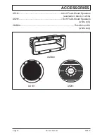
Page 18: ...Page 16 Owner s Manual MST70 ACCESSORIES AS101 6 inch Flush Mount Speakers available in black or white AS201 7 inch Flush Mount Speakers white only CMB60 Flush Mount Kit white only AS101 AS201 CMB60 ...

Page 19: ...mited warranty does not extend to any Product which has been subjected to misuse neglect accident improper installation or subject to use in violation of the maintenance of operating instructions if any furnished by STANDARD HORIZON nor does this warranty extend to products on which the serial number has been removed defaced or changed STANDARD HORIZON reserves the right to make changes or improve...

Page 20: ...Marine Division of Yaesu U S A 17210 EDWARDS ROAD CERRITOS CA 90703 Telephone 562 404 2700 STANDARD HORIZON 1999 ALL RIGHTS RESERVED PRINTED IN CHINA January 2000 ...

Reviews: