background image

4

1

2

3

4

5

6

APC-45 Knife Replacement

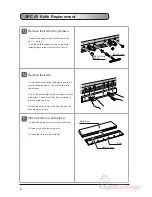
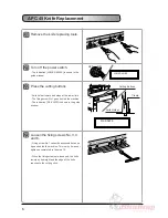
Remove the knife fixing screws.

- Remove the fixing screws at the screw holes

No.1, 3, 4 and 6.

- Now the knife is supported only by the knife

replacing tools at the screw hole No.2 and 5.

Remove the knife.

1) Hold the knife replacing tools tightly and turn it

counterclockwise slowly. You will feel the knife

comes loose.

2) Turn  the knife replacing tools counterclockwise

a bit further. The knife will be held completely by

the knife replacing tools.

3) Move the knife slowly to the right, then down-

ward along the groove.

Place a knife in a safe place.

1) Attach the safety cover on the removed knife.

2) Remove the knife replacing tools.

3) House the knife into the knife box.

Knife Box

Knife

Safety Cover

Box Wrench

Knife Fixing
Screw

1

2

3

4

5

6

Summary of Contents for APC-45

Page 1: ...Knife Replacement Guide Provided By http www MyBinding com http www MyBindingBlog com Standard APC45 Programmable Paper Cutter ...

Page 2: ...into the cutting stick too deeply when installing the new knife instead of the re sharpened knife APC 45 Knife Replacement The knife must be replaced by just one person at a time Wear gloves and do not touch the knife The knife may cause severe personal injury Be careful for the removed knife Do not place the removed knife on the unstable floor or place where knife edge is exposed WARNING Knife re...

Page 3: ...k on the knife holder aligns to the bottom of the frame when you see the mark horizontally Insert the screwdriver accessory into the hole on the turn buckle and rotate it Tighten two lock nuts Close the lower cover APC 45 Knife Replacement Wrench Locking Nut Loosen Loosen Loosen Screwdriver Accessory Hole Lowers Knife Holler raises Side View Frame Knife Holder See horizontally Check using the scal...

Page 4: ...les No 2 and No 5 WARNING Tighten the tools by hand as much as possible The knife will be supported just by these two tools when removing the knife APC 45 Knife Replacement OFF ON KNIFE REPLACE MODE LOWER CLAMP TURN OFF POWER REPLACE KNIFE OFF ON Clamp Knife Cutting Buttons NOTE If the knife replacing tool cannot be screwed because the screw hole is as shown in the figure above 1 Loosen the knife ...

Page 5: ...turn it counterclockwise slowly You will feel the knife comes loose 2 Turn the knife replacing tools counterclockwise a bit further The knife will be held completely by the knife replacing tools 3 Move the knife slowly to the right then down ward along the groove Place a knife in a safe place 1 Attach the safety cover on the removed knife 2 Remove the knife replacing tools 3 House the knife into t...

Page 6: ... fall Or if the space is too small the knife cannot be installed to the knife holder Install the knife 1 Hold the knife replacing tools tightly and move the knife upward slowly then to the left along the groove on screw hole No 2 and 5 2 Stay the knife there and turn the knife replac ing tool clockwise to lock the knife Install the fixing screws Tighten the screws No 3 4 and 6 tightly Tighten the ...

Page 7: ...stops at the lower limit The fixing screw No 1 goes behind the machine The indication FIX KNIFE is shown in the guide window Loosen the fixing screws No 3 4 and 6 Fixing screw No 1 cannot be accessed because it goes behind the machine This is why it was not tightened completely in the step 19 When the fixing screws are loosened the knife lowers by its weight and the edge of the knife reaches to th...

Page 8: ...ove can be seen through the window This is the knife angle adjusting screw Adjust the knife angle In case of S N323899 or below Adjust the direction and angle of the knife by the positional relation of the groove shown in the figure below and mark The standard position is as shown in the figure below In case of S N324001 or above Adjust the direction and angle of the knife by changing the position...

Page 9: ...g screw Tighten the fixing screws No 3 4 and 6 NOTE Insert the box wrench and move it down ward and turn clockwise to lock the screws Fasten the screws completely in order Press the cutting buttons sepa rately Provide 0 5 seconds or more interval between The motor drives in reverse The knife holder raises and then the clamp raises The indication FIX KNIFE ATTACH KNIFE COVER is shown on the guide w...

Page 10: ...uide window Press the Ent key When is pressed the back gauge move to the 400 0 position and the Normal Work Mode is selected Knife replacement is complete Perform the test cutting If some of the sheets remains uncut go to 4 1 knife Lower Limit Adjustment in the operation manual COMPLETE PRESS Ent Knife Cover Ent 7 8 9 C 4 5 6 1 2 3 Ent 0 ...

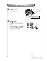
Page 11: ...10 ...

Reviews: