background image

Summary of Contents for CV110

Page 1: ...OPERATING INSTRUCTIONS CV110 2mFM VFO ...

Page 2: ...ed with utmost care through our advanced techniques and ample experience in the field of FM transceivers so as to assure your everlasting satisfaction CONTENTS 1 Introduction 2 2 Features 2 3 Operating Parts 4 4 How to Use 5 5 Timing Meter 6 6 CAL Knob 6 7 RTT Knob 6 8 Precaution for Mobile Station Operation 7 9 Specifications 8 10 Block Diagram 9 11 Circuit Diagram 10 1 ...

Page 3: ...ibration resistant Design Due to the development bf fully isolated oscillator block covered with a plate of 1 2mm thich CV 110 is highly resistant against vibrations The QSO is comparable to that of crystal oscillator even when the imit is used as a mobile Station 4 Excellent Frequency Stability The employment of MOS FET in the clap circuit and the use of slit steatite bobin loch type air trimmer ...

Page 4: ...e is being in use in your band 9 CVrllO incorporates newly adopted glass epoxi printed circuit board for better operational Performance 10 Green Lamp Illumination The meter and dial are illuminated green This protects the Operator from dazzling light and assures safe driving of car at night 11 Removable Stand The removable stand is used when the unit is operated as a fixed Station 3 ...

Page 5: ...3 Operating Parts Tuning Meter CD Tuning Knob D Dial 0 CAL Knob D KIT Knob Stand CAL IT ...

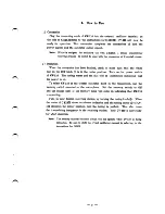
Page 6: ... The tuning meter and the dial will be illuminated indicating that the power is on To select CV 110 or the crystal oscillator built in the transceiver use the memory switch mounted on the microphone Set the memory switch to ON and the orange light of the memory lamp will come on indicating that CV 110 is operating Tune in your desired receiving Station by turning the tuning knob 2 When the meter o...

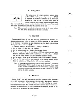
Page 7: ...on the microphone to OFF and confirm that the signal from the transmitting Station can bs caught by the crystal oscillator inC828M and that the tuning meter of CV 110 is indicating the center position 4 Set the memory switch on the microphone to ON so that CV 110 is operated 5 Turn the CAL knob slowly to tune accurately to the opposite transmit Station Now the calibration of dial graduation will h...

Page 8: ...tion for Mobile Station Operation For the purpose of safe driving please avoid using CV 110 for QSY while the car is running To ensure pleasant driving the use of the crystal oscillator inC828M is recommended 7 ...

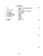
Page 9: ...tage 5 KIT Adjustable Range 6 CAL Adjustable Range 7 Semiconductors 8 Dimentions 9 Weight VFO for 2m band FM amateur transceiver C828M 144 W146 0MHz Output frequency 30 50 31 00 MHz Less than 250mA More than 10mV 5KHz 20KHz 2FETs 4transistors 4diodes 84x58x235 mm 1 0kg 8 ...

Page 10: ...10 Block Diagram BUF TRIP OSC BUF REGULATOR 9 ...

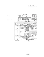
Page 11: ...w t i I icoos 2000P h C006 2000P J202 5 J20I 5 P20I Buffer Regulator PWB BUFFER Q202 2SC387Ng M3 8V TRIPLER Q20I 2SC535B SWITCH R209 4 7K J202 1 J20I I a55V 8 0 c 02042SA67 1 15V lYYyTo J202 2 J20I 2 L20l 390 h R223 330 S20 RELAY 8 9 V laev FRONT PANNEL 9 5V J202 3 J20I 3 O N CM CM CM 0 0V J202 4 J20I 4 10 ...

Page 12: ...0I02 2SKI9 JFFER o ev CIIS lOOP II C007 X 2000 LI03 390 h I 5D 2V R2I4 0K R2I6 80 R2IS I00 Q 0205 QS sei213 0 OUT PUT MIO HOT MEMO OSO E SWITCHED B Tx B CENTER METER GROUNO OC VOLTAGE SWITCH ON OFF 3775 851 020 ...

Page 13: ...nz ein und verändert den Regler CAL solange bis das Meß instrument den Nttlldurchgang des Diskriminators anzeigt Der Variationsbereich dieses Reglers ist ca 125 kHz Bei größeren Abweichungen kann eine Frequenzkorrektur nur an den frequenzbestimmenden Teilen des Oszillatorschwingkrcises vorgenommen wexiden Achtung Nach erfolgter Eichung Stellung des Reglers merken Für 9mplex Verkehr wird der VFO zu...

Reviews: