


(4)
スト
ッパ
の移
動方向
ストッパの移動方向
L
S
S
L
2
2 ス
トッパ
ストッパ
1
1 ス
トッ
パ
ストッパ
テスト
スタート
/ストップ
折形
紙サイ
ズ
B 5
B 4
A 4
A 3
二つ
四つ
片袖
観音
内三つ
外三つ
クリア
排紙状
態で
表わし
て、
ありま
す。
部
長
い
部
短
い
排紙状
態で
表わし
て、
ありま
す。
部
長
い
部
短
い
2 スト
ッパ
1 ス
トッパ
外三つ
折
L
S
外三つ
折
L
S
二つ折
二つ折
L
S
片袖折
S
L
片袖折
L
S
内三つ
折
L
S
内三つ
折
S
L
観音折
L
S
観音折
S
L
ストッ
パの微
調整方
法
四つ折
S
L
四つ折
L
S
0
10
15
20
25
30
5
二つ折
片袖折
内三つ
折
観音折
四つ折
紙のセ
ット
*印刷
面はウ
ラ向き
です。
外三つ
折
ストッ
パの移
動方向
L
S
1 スト
ッパ
2 スト
ッパ
10
10
15
15
20
20
25
25
30
30
5
10
10
15
15
20
20
5
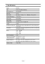
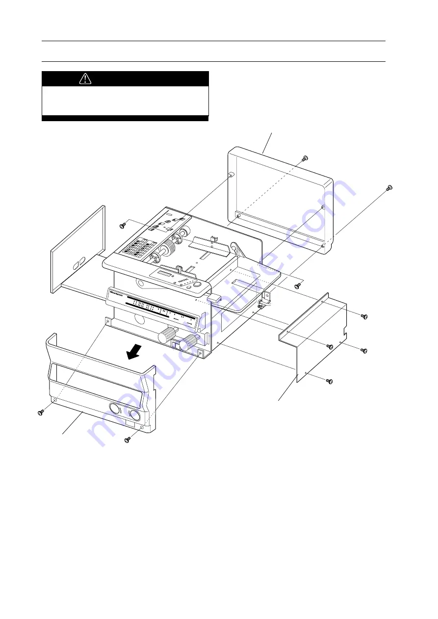
PF-P310
PEPER FOLD
ER
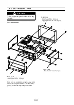
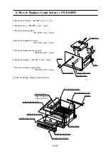
Front Cover
- Bind Screw M4 x 8 (2 pcs)
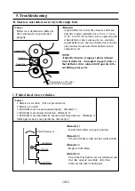
Front cover is installed with the top edge fitted
with operation panel. Remove front cover by
pulling front cover diagonally downward.
Side Cover
- Bind Screw M4 x 8 (4 pcs)
4. How to Remove Cover
Rear Cover
- Bind Screw M4 x 8 (2 pcs)
- Tapping Screw M4 x 10 (2 pcs)
Tool : Screwdriver
CAUTION
- Turn off main power and remove any
covers.


